EP1001
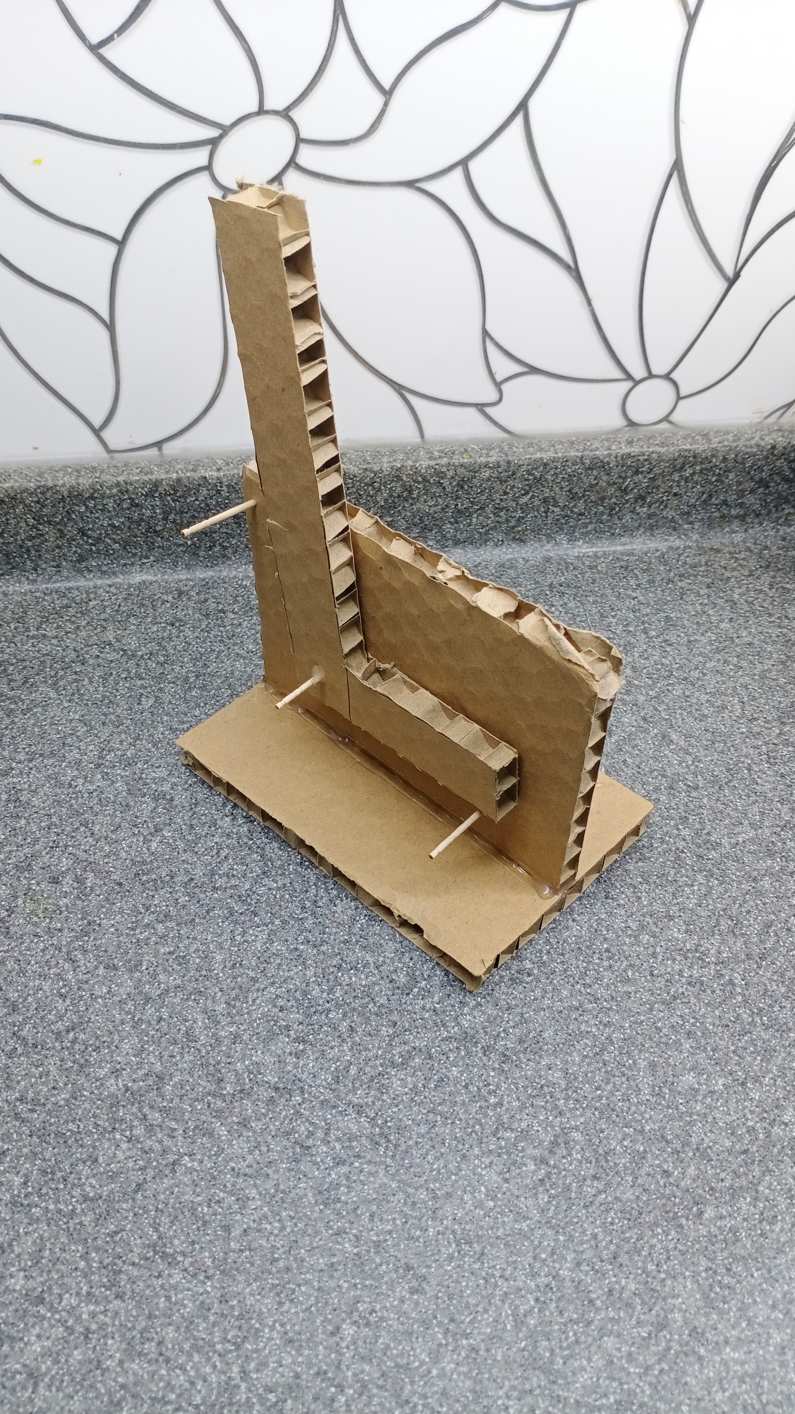
Project
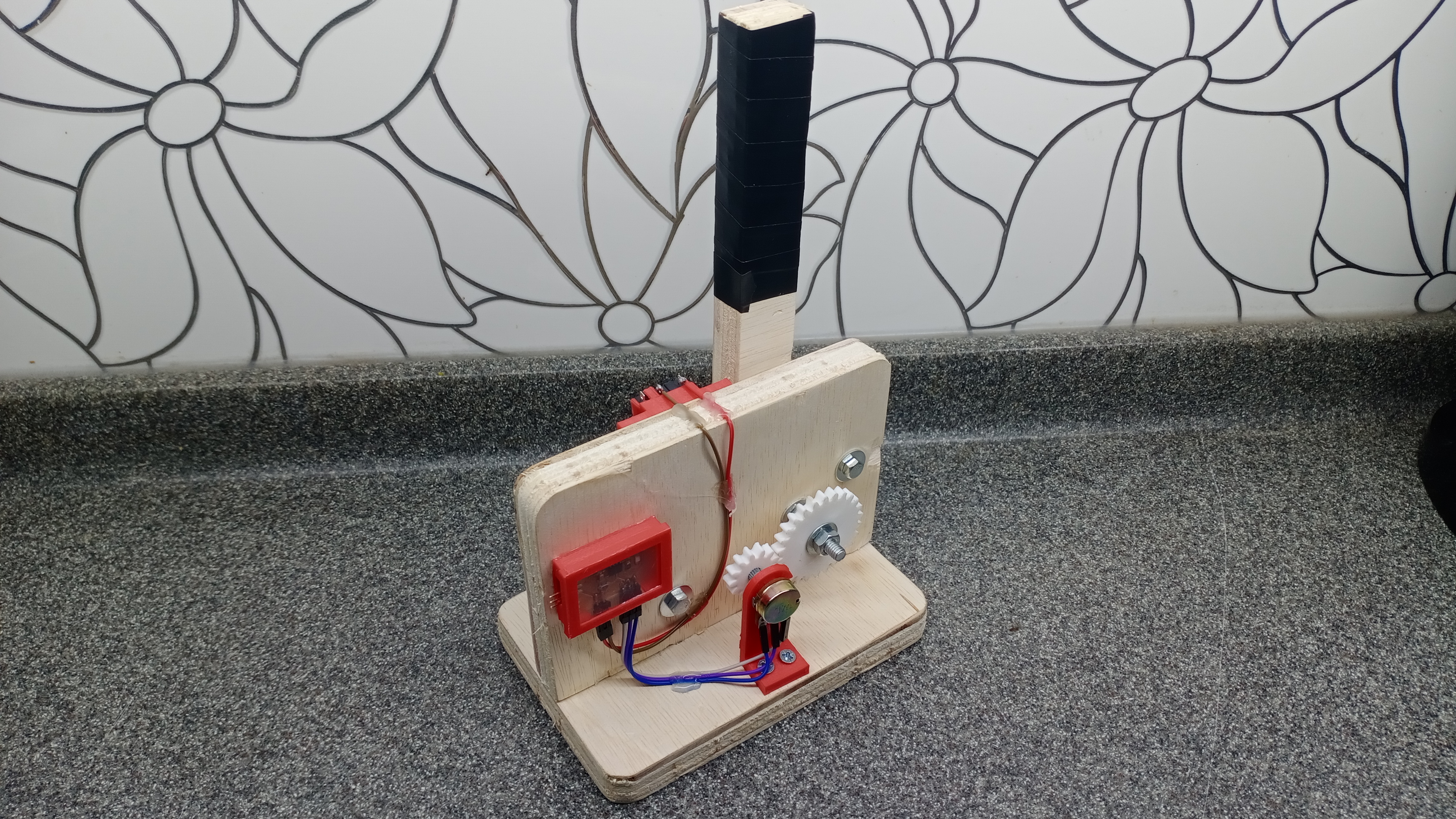
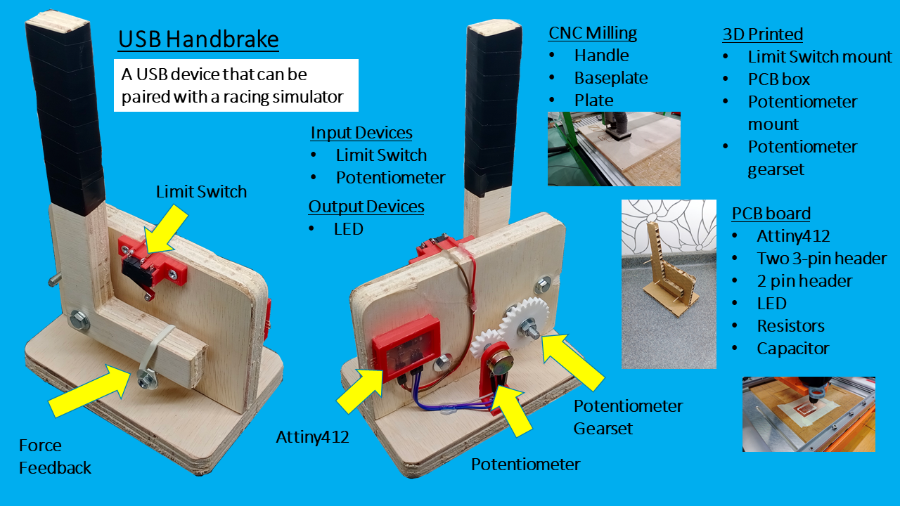
I decided to make a USB Handbrake. This can be used with a racing simulator, It will be connected to the computer through USB. Here is the concept diagram and prototype:
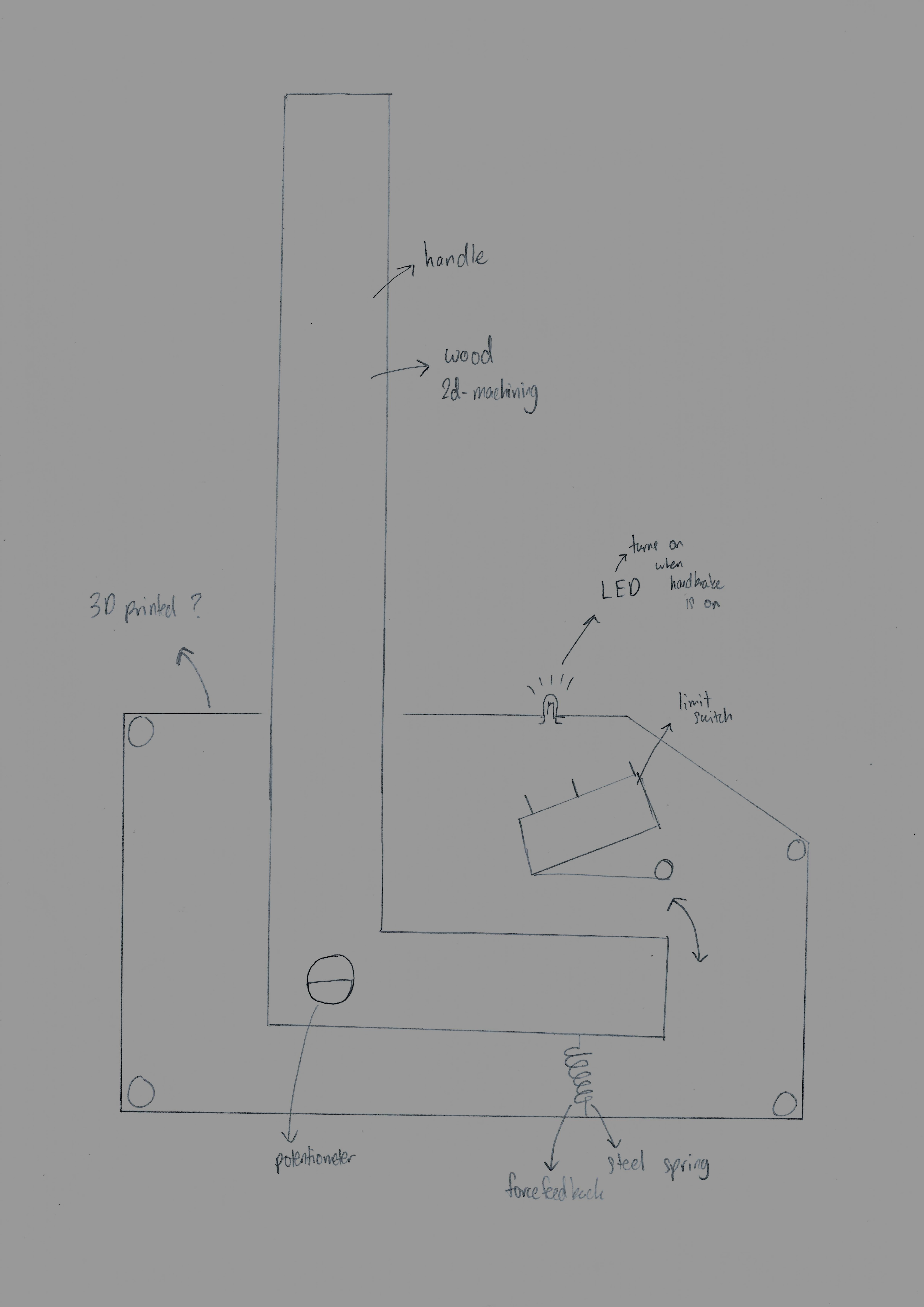
Components I need:
- 10K potentiometer
- Limit switch
- LED
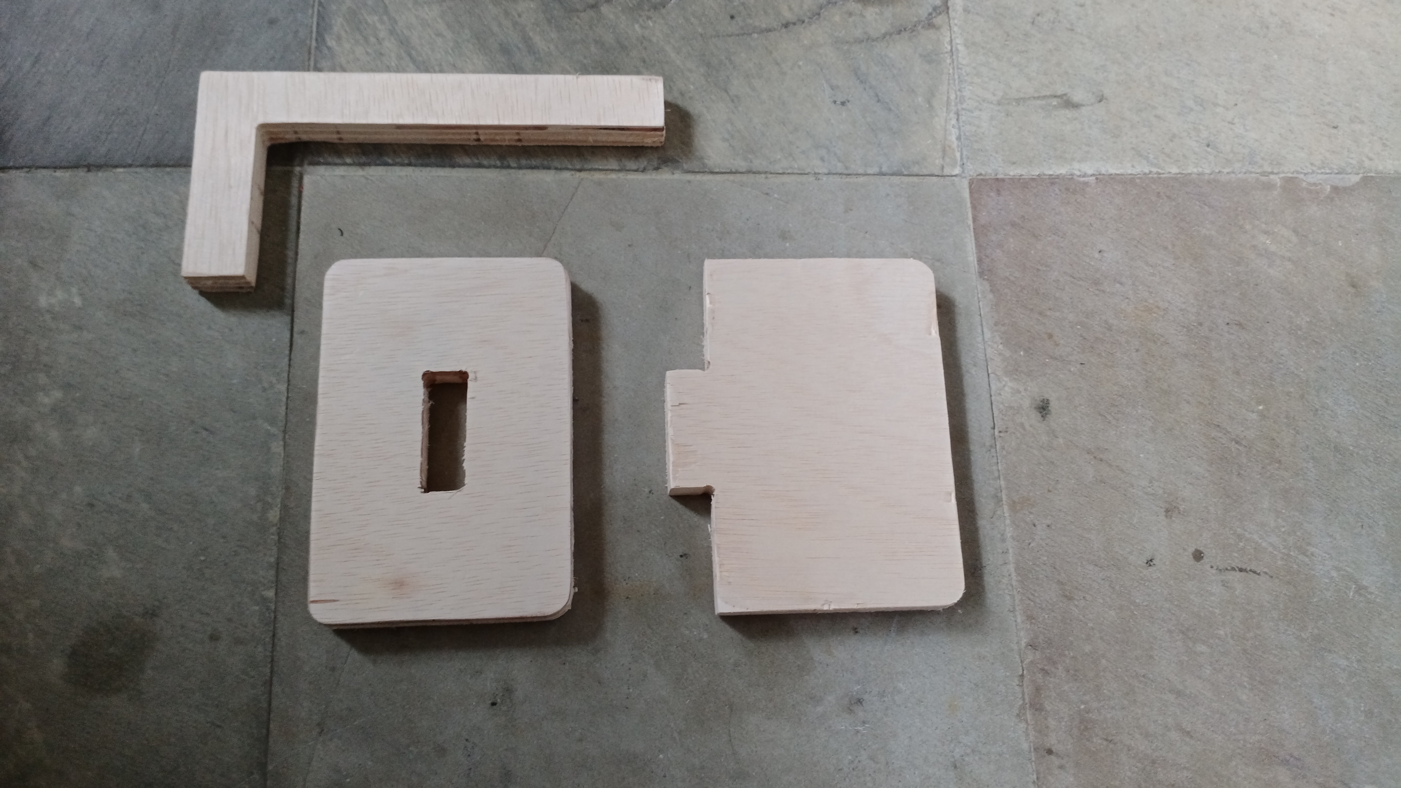
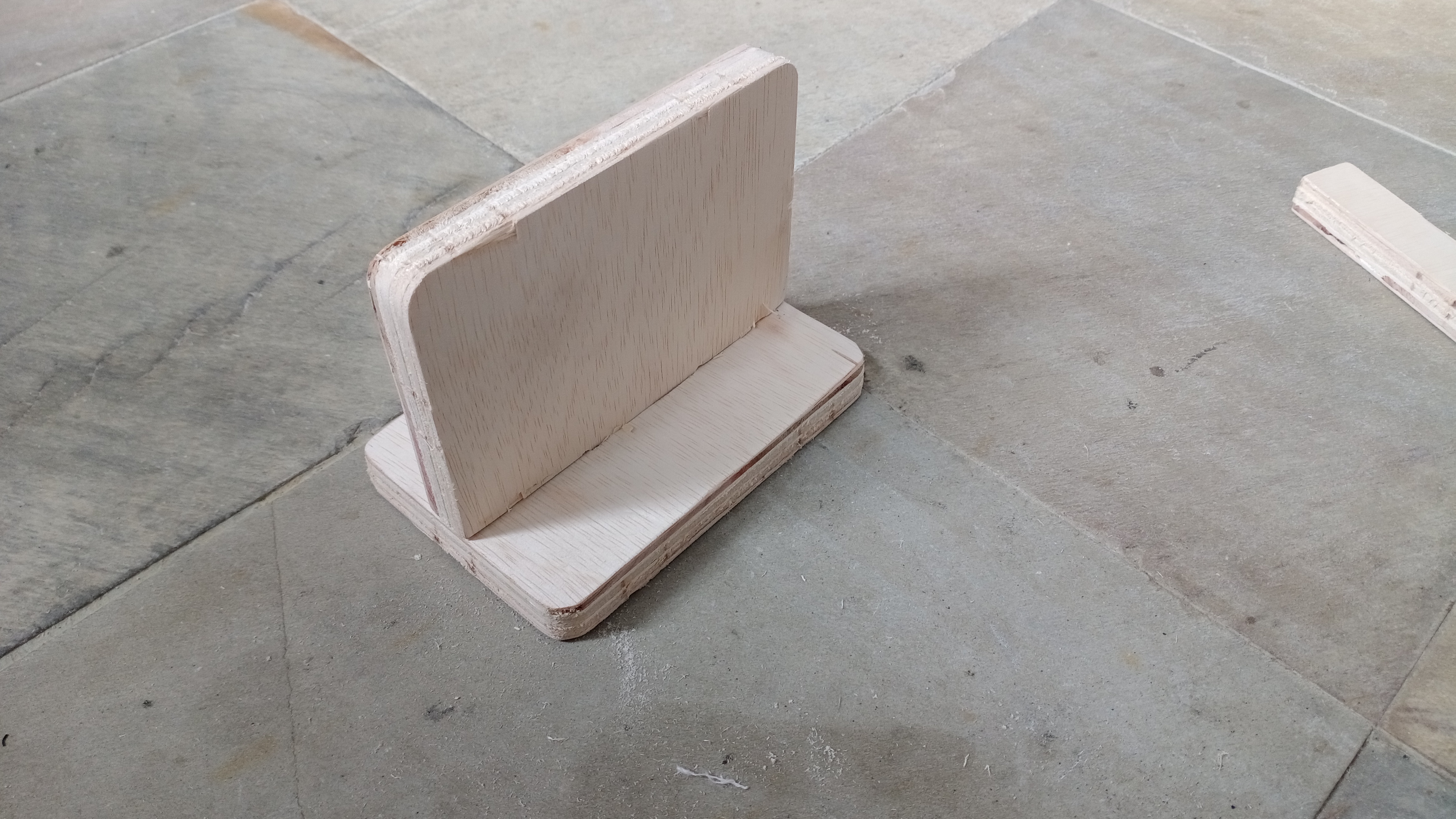
The handbrake itself will made of wood as it needs to be strong. Thickness of the wood I’m using is 18mm. I’ll be using the CNC mill to fabricate it. Here are the designs and layout:
.png)
Handle
.png)
.png)
Plate
.png)
.png)
Baseplate
.png)
.png)
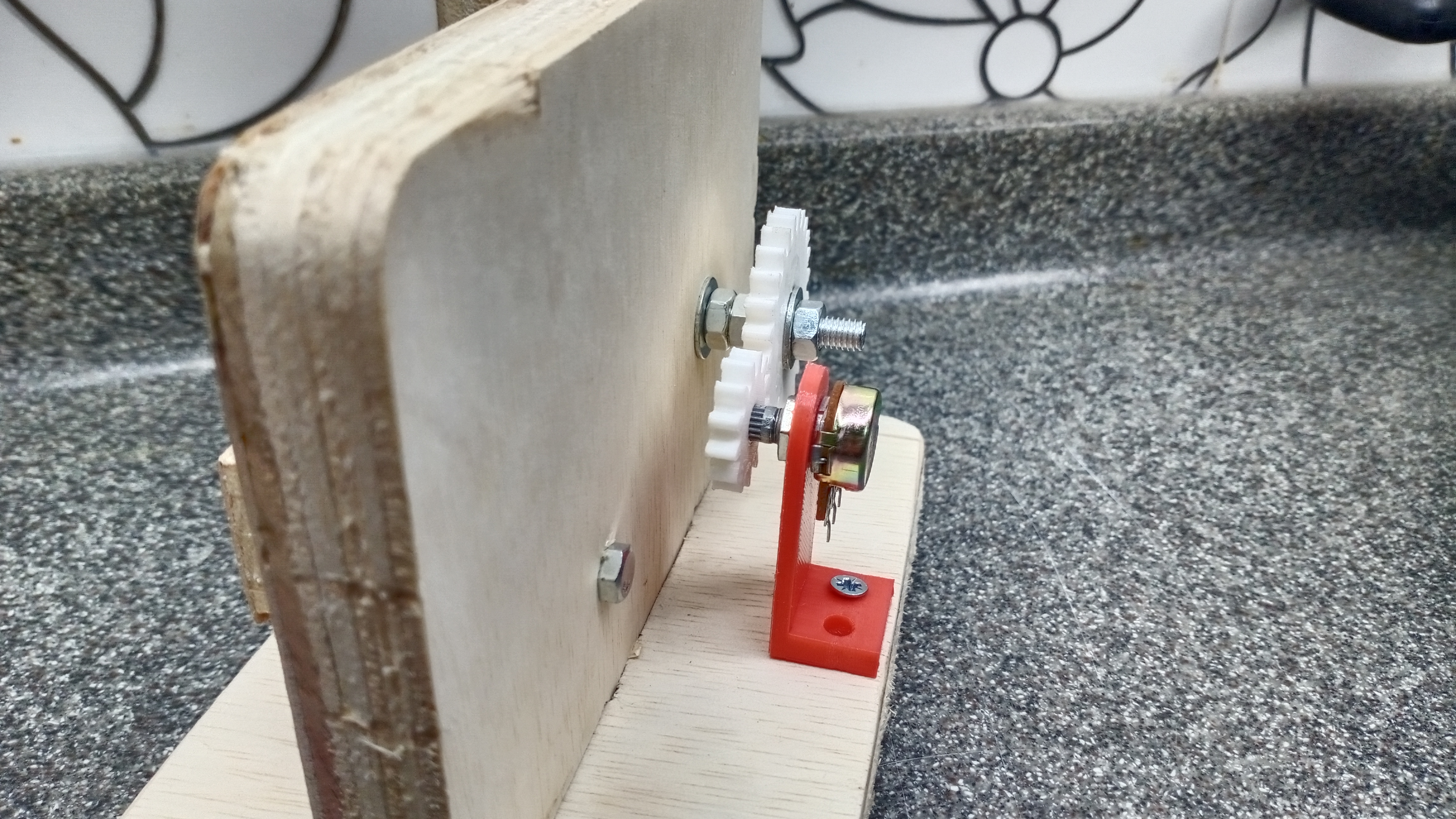
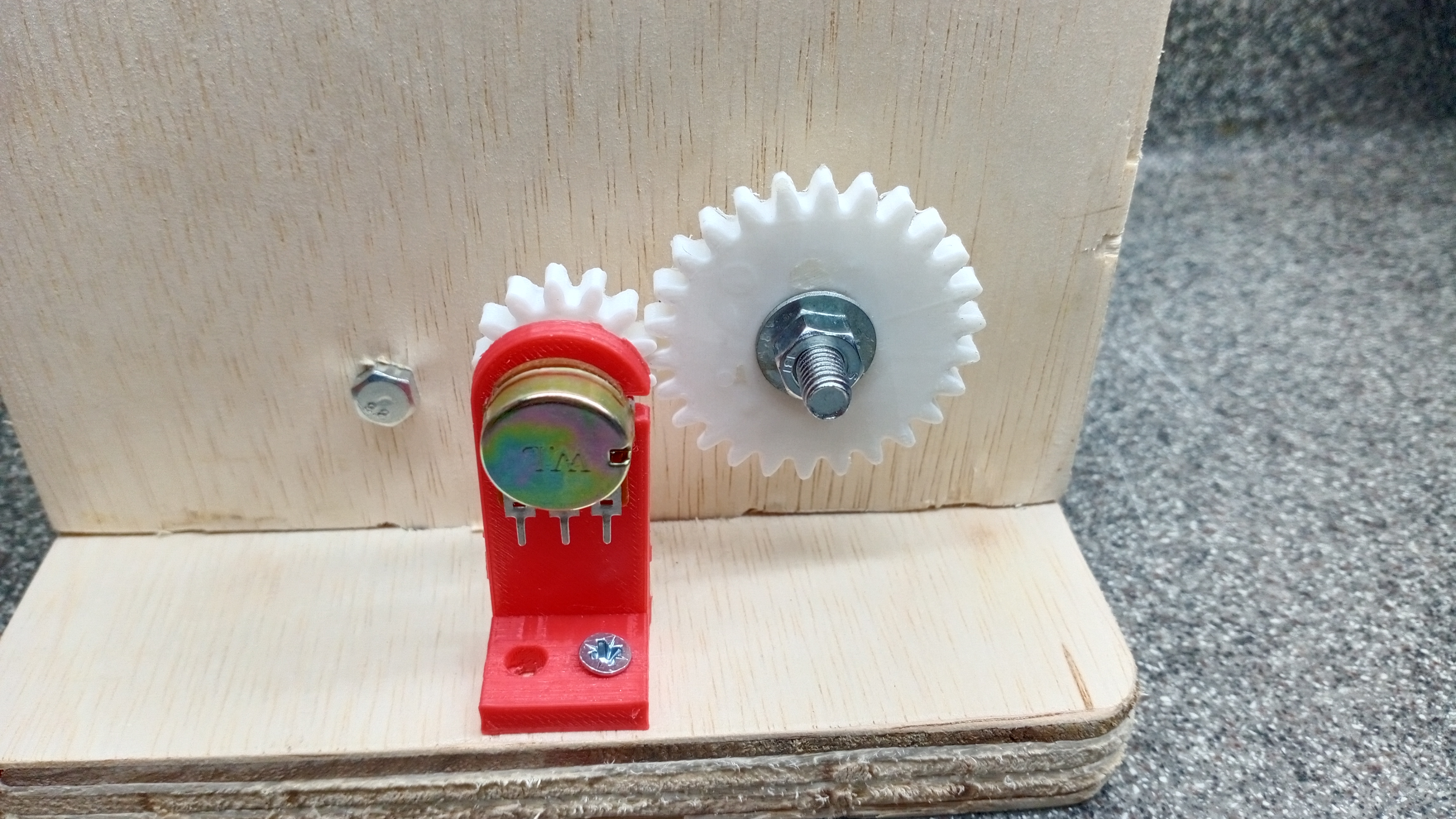
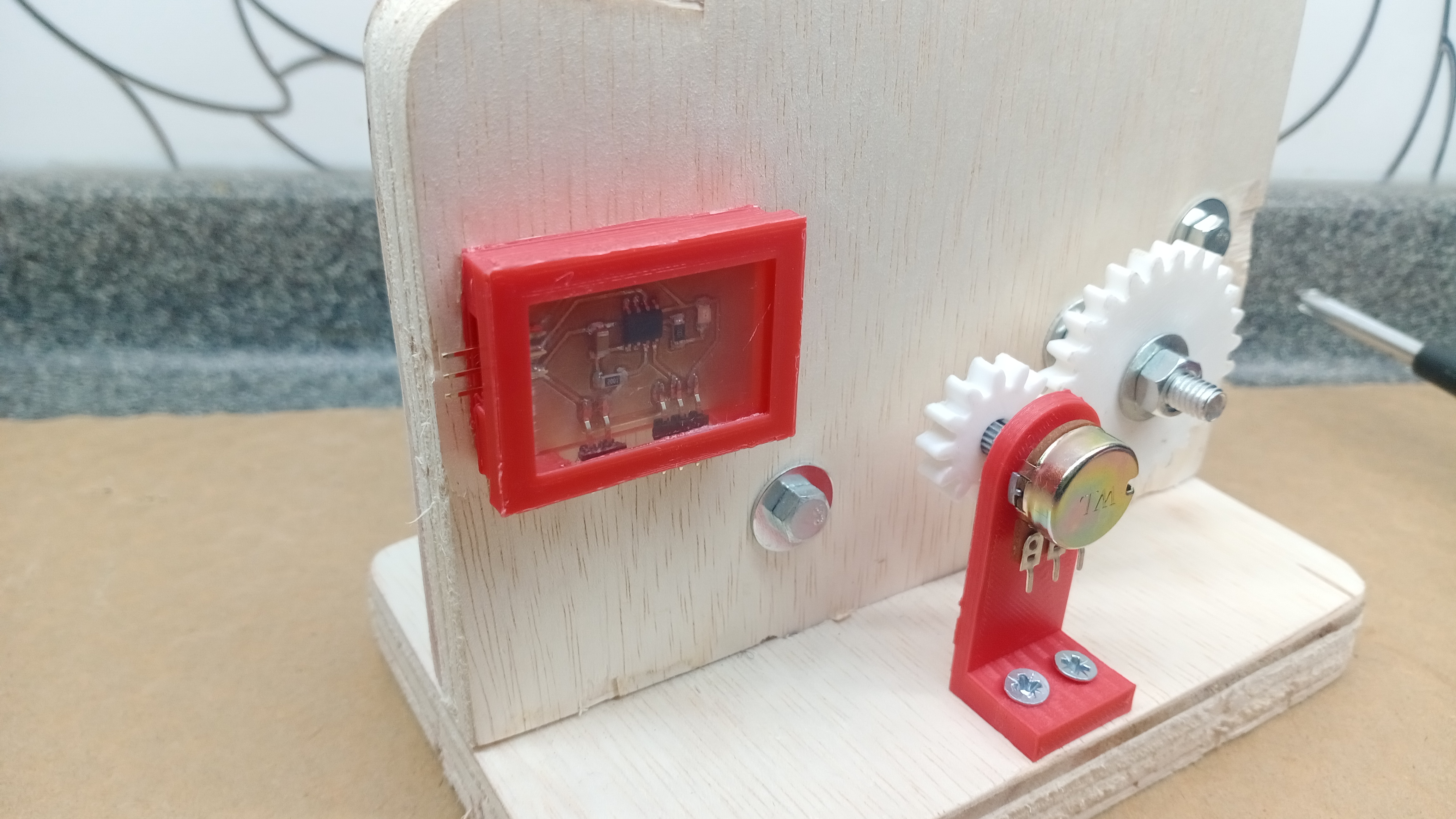
Gearset Potentiometer
I’m using the gearset to help transmit the movement of handle to the potentiometer.
.png)
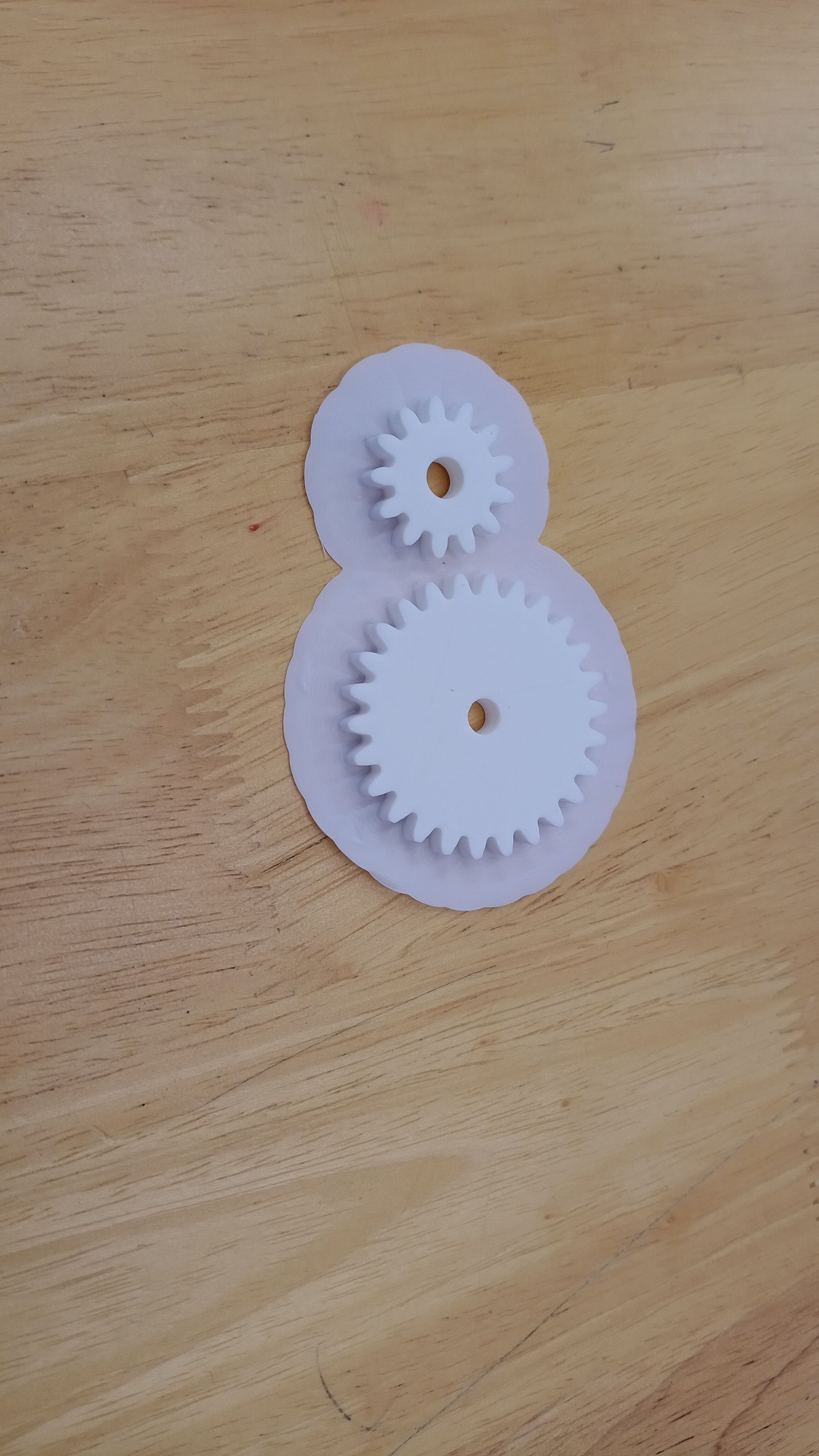
I used the Spur gear tool in add ons to create the gearset. The bigger gear has 26 teeth with pcd of 39mm. The smaller gear has 13 teeth with pcd of 19.5mm
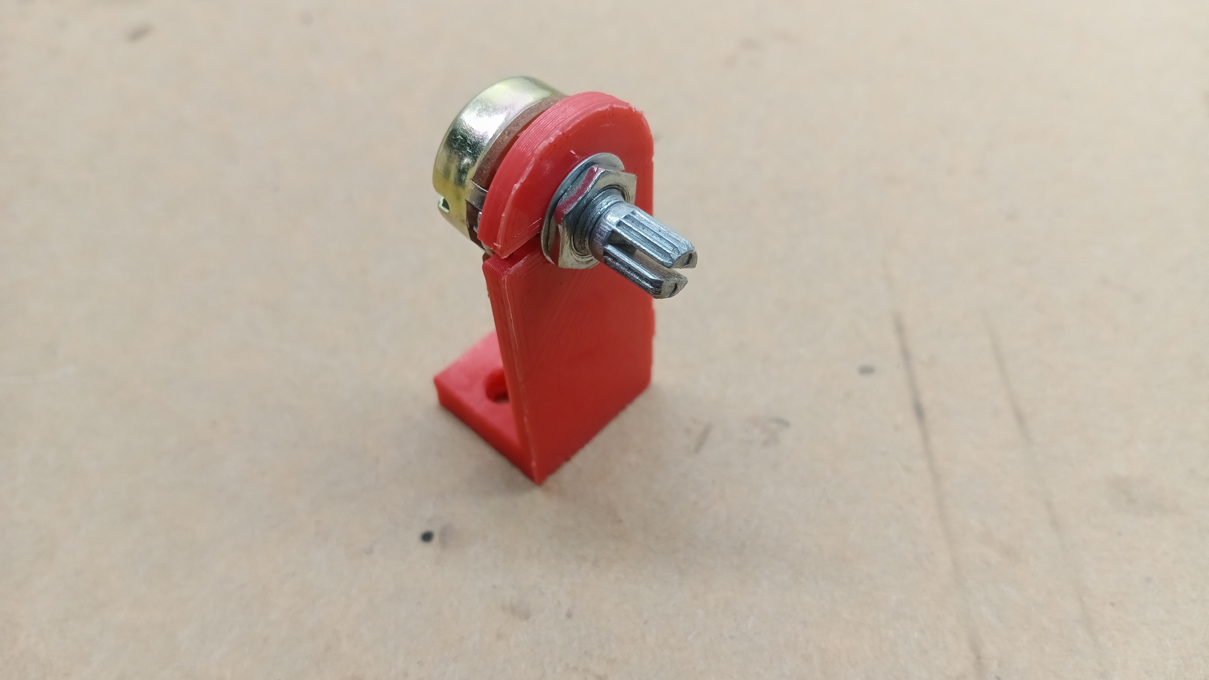
Potentiometer Mount
.png)
.png)
This is a mount for the potentiometer so that it stays in place. It will be attached to the smaller gear. The slot is clearance for the small notch on the potentiometer.

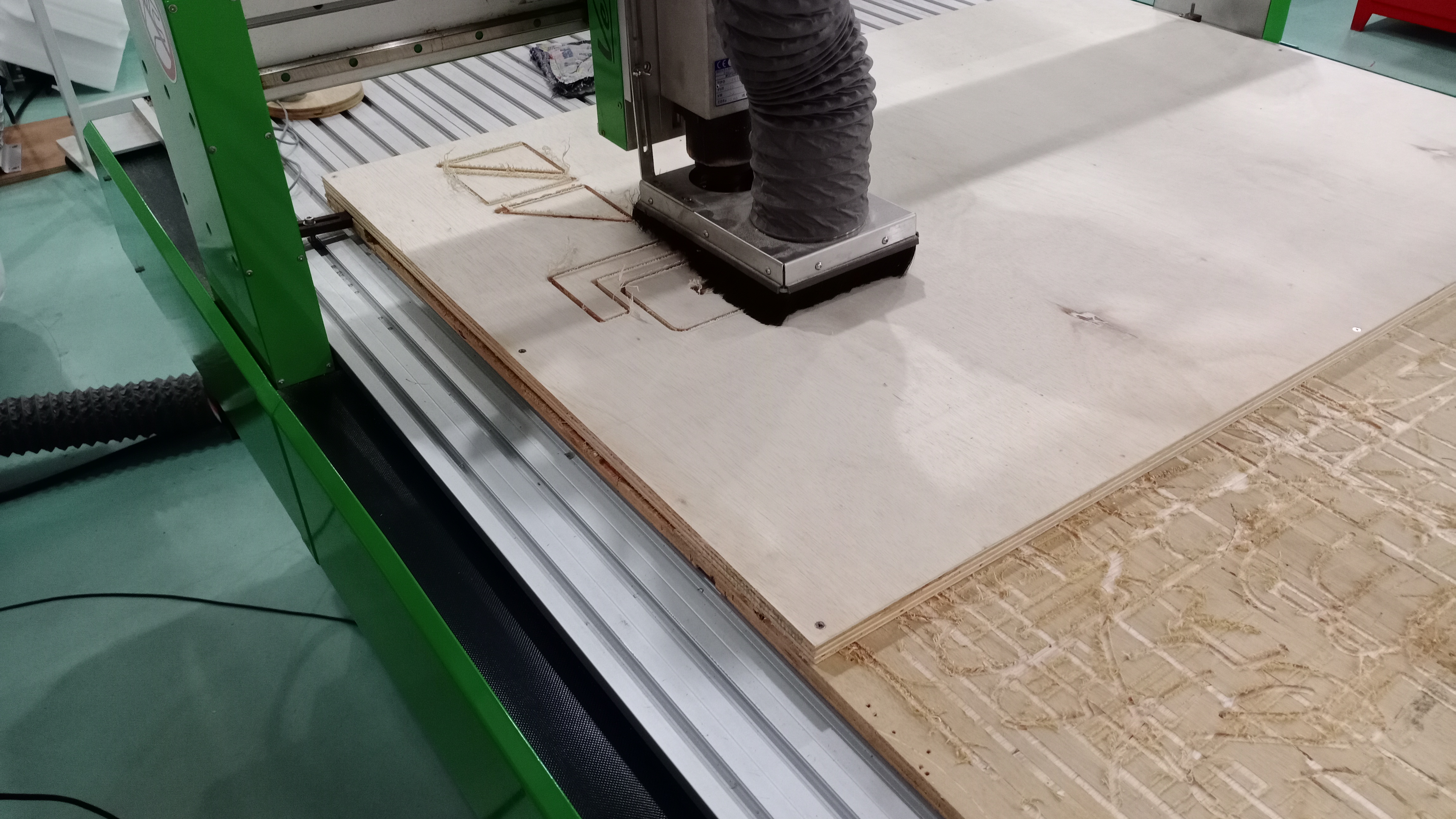
CNC Milling
I’m using CNC milling to fabricate the main frame.
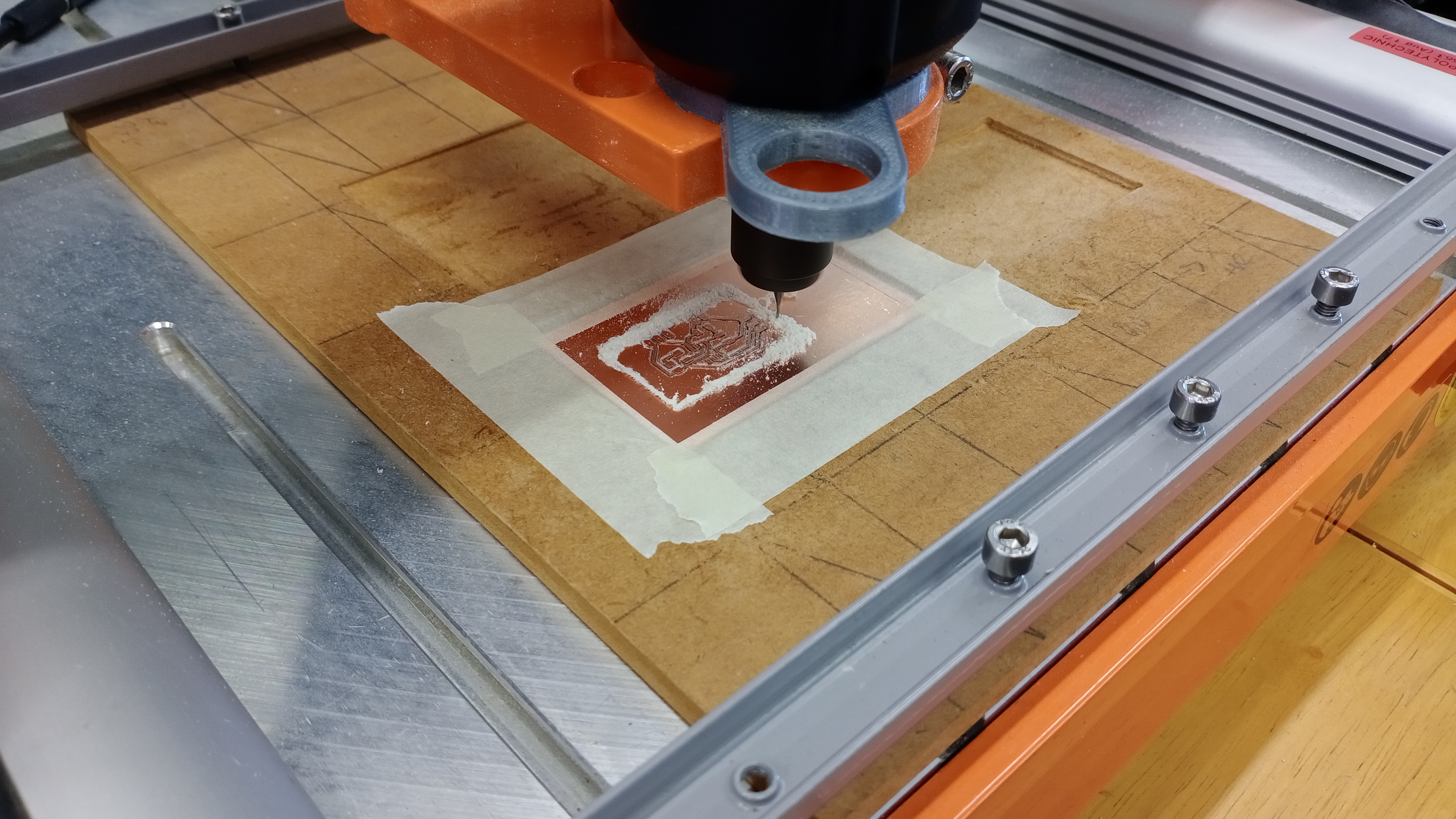
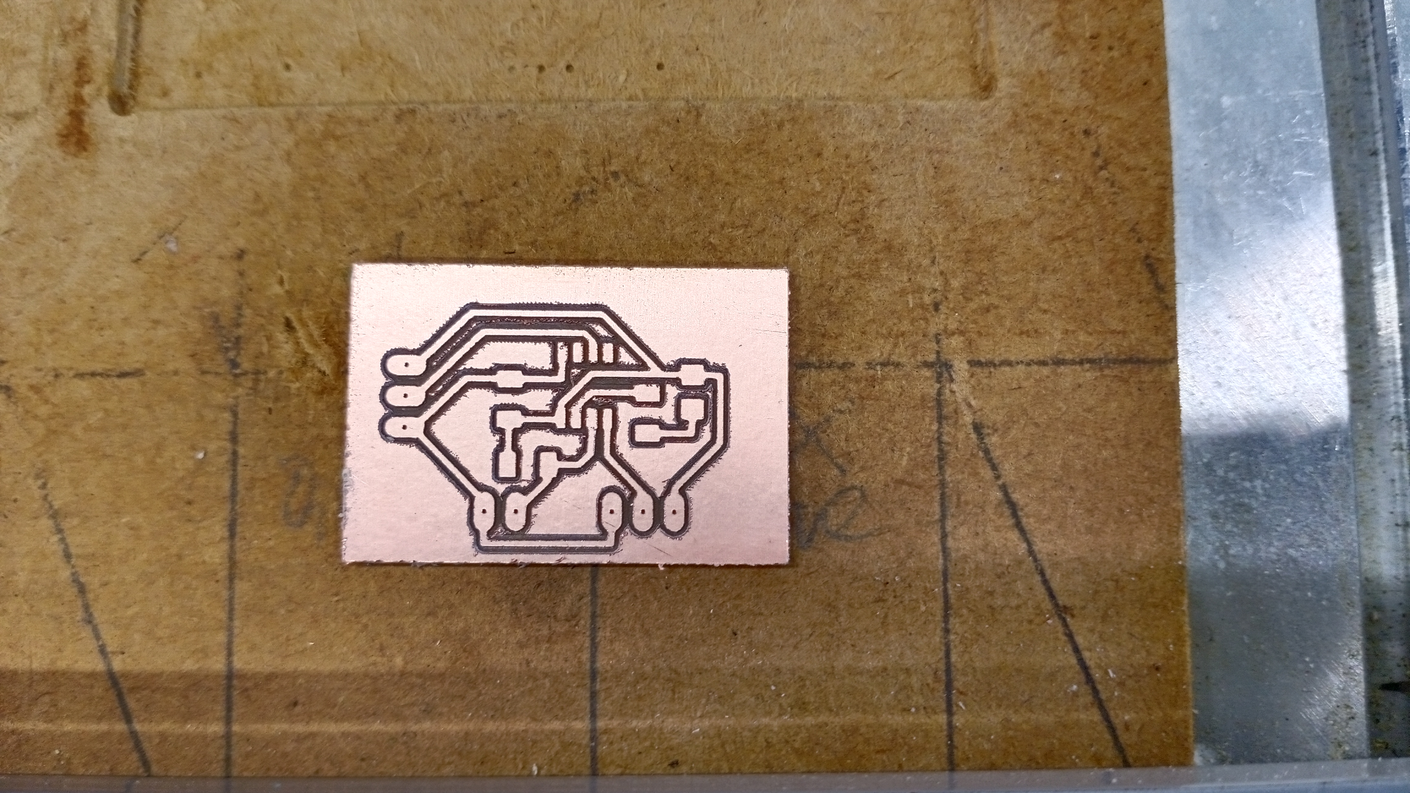
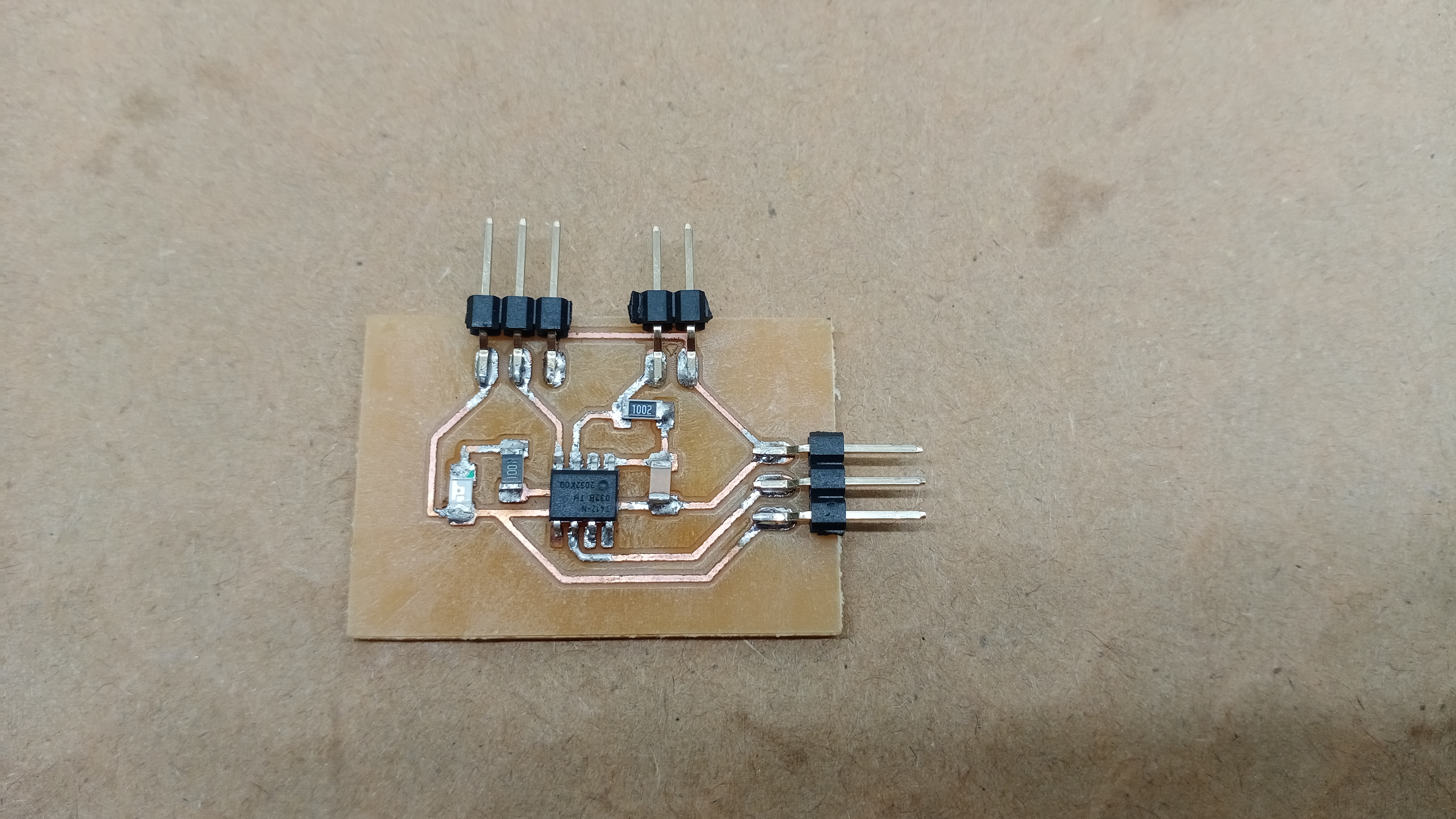
PCB board
Inputs devices will be the potentiometer and the limit switch. An LED will be the output device. I’m using the Attiny412 as the microcontroller. There will be two 3pin header for the UPDI and potentiometer. Limit switch is connected to the board through 2pin header. The limit switch requires a 10k resistor. LED also uses a 1k resistor.
.png)
.png)
The board dimension is 26mm by 36mm. When milling the board, make sure to use offset cut as this will make it easier to solder the components.
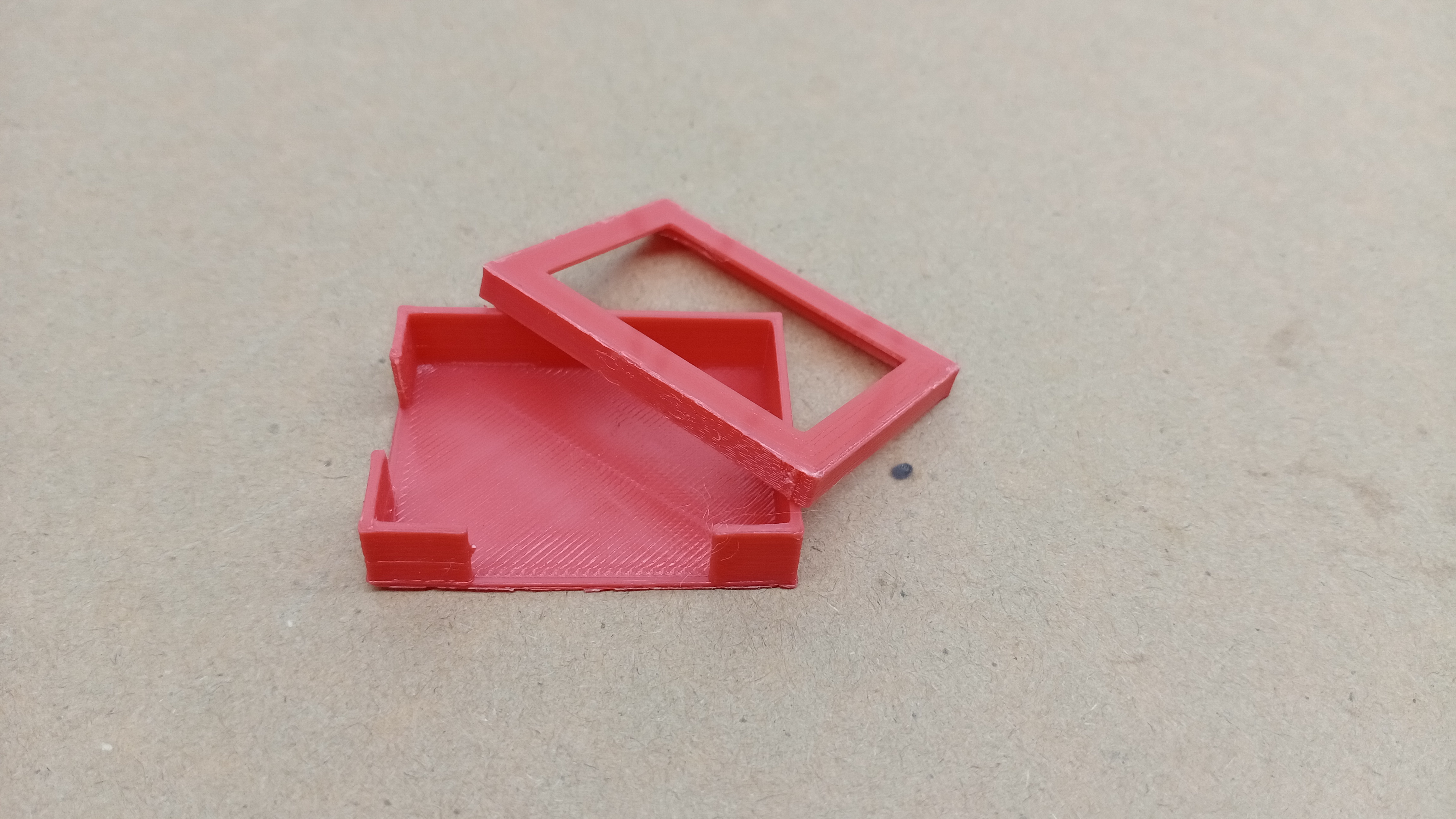
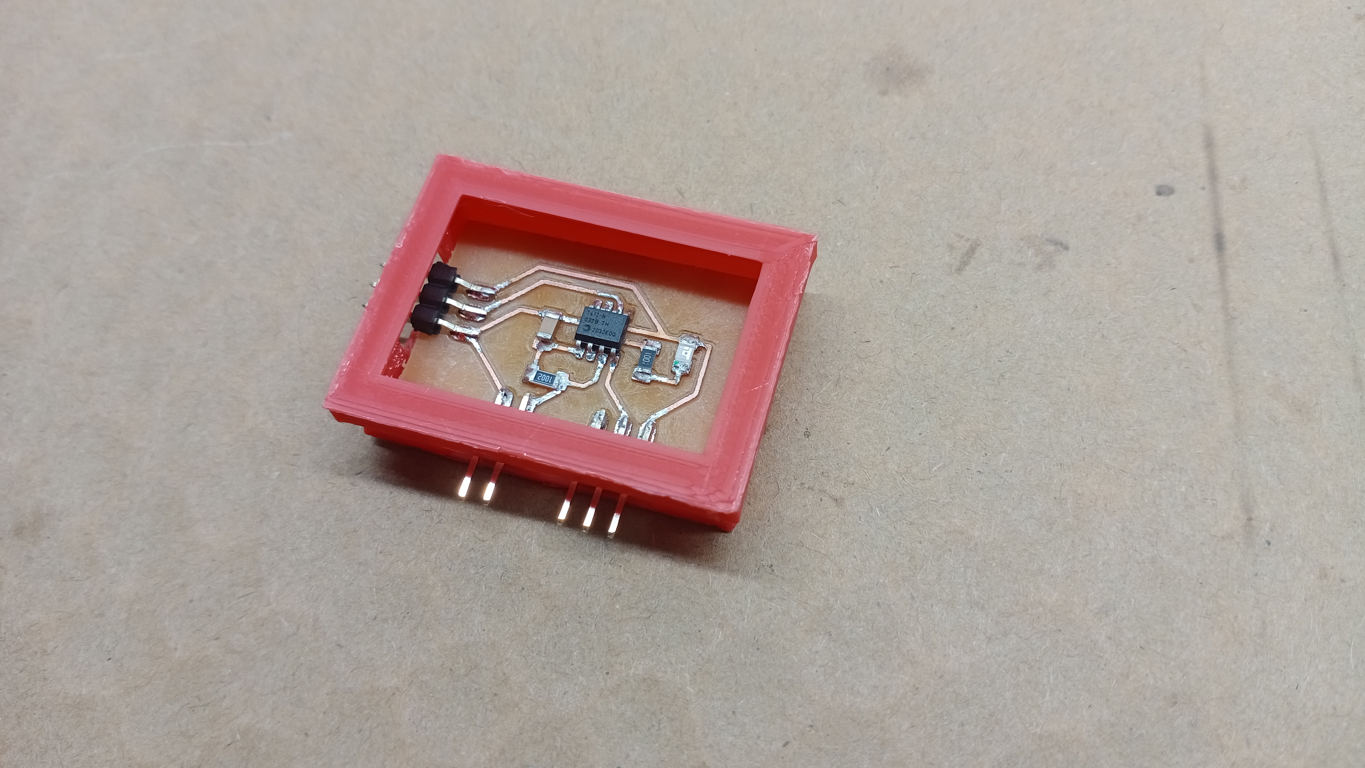
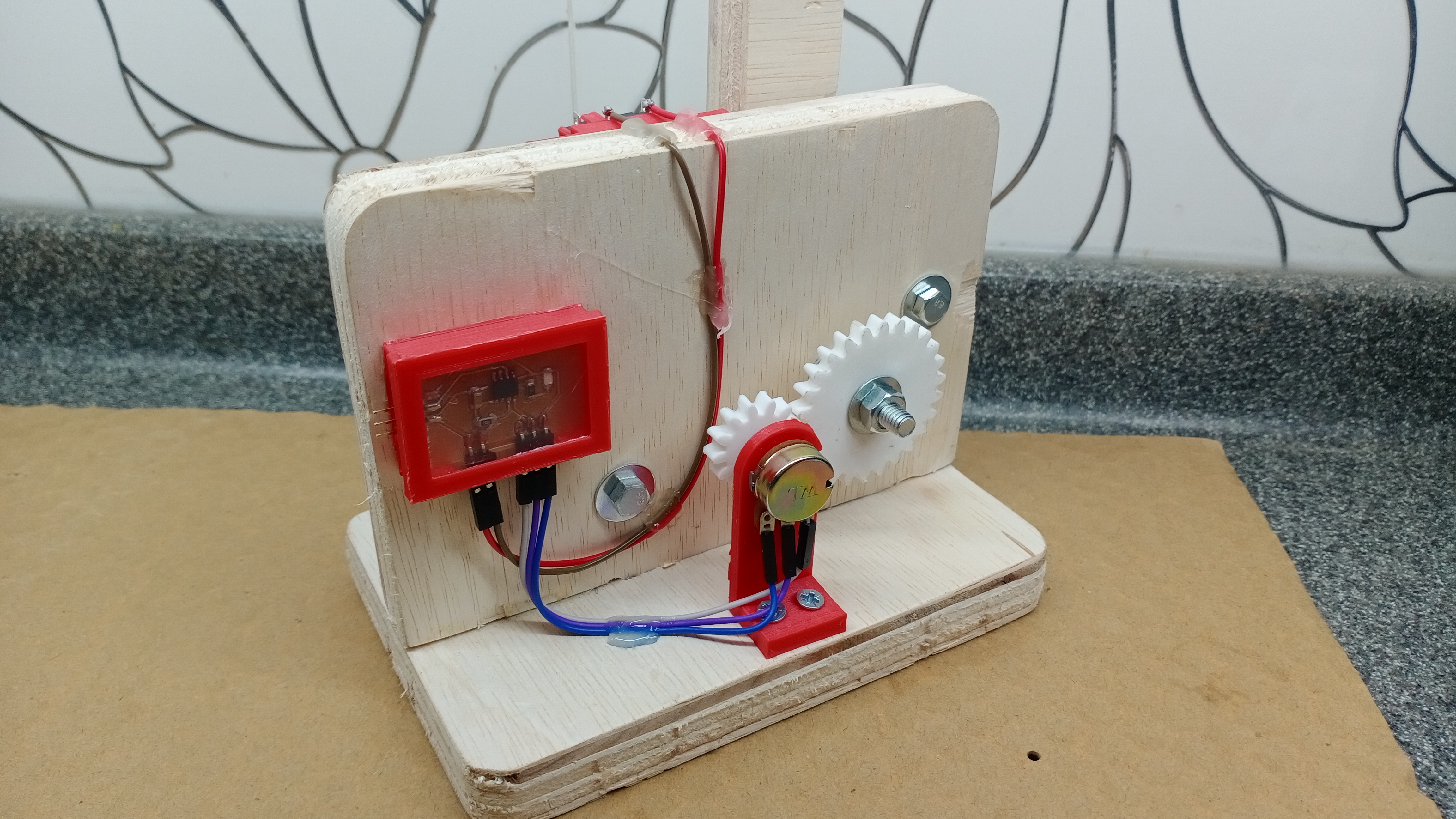
PCB box
I design a box for the PCB board to make it look clean. Since there is an LED on the board, I decided to make a hole on the cover. I’ll use a plastic sheet to cover it up so that the LED will be visible
.png)
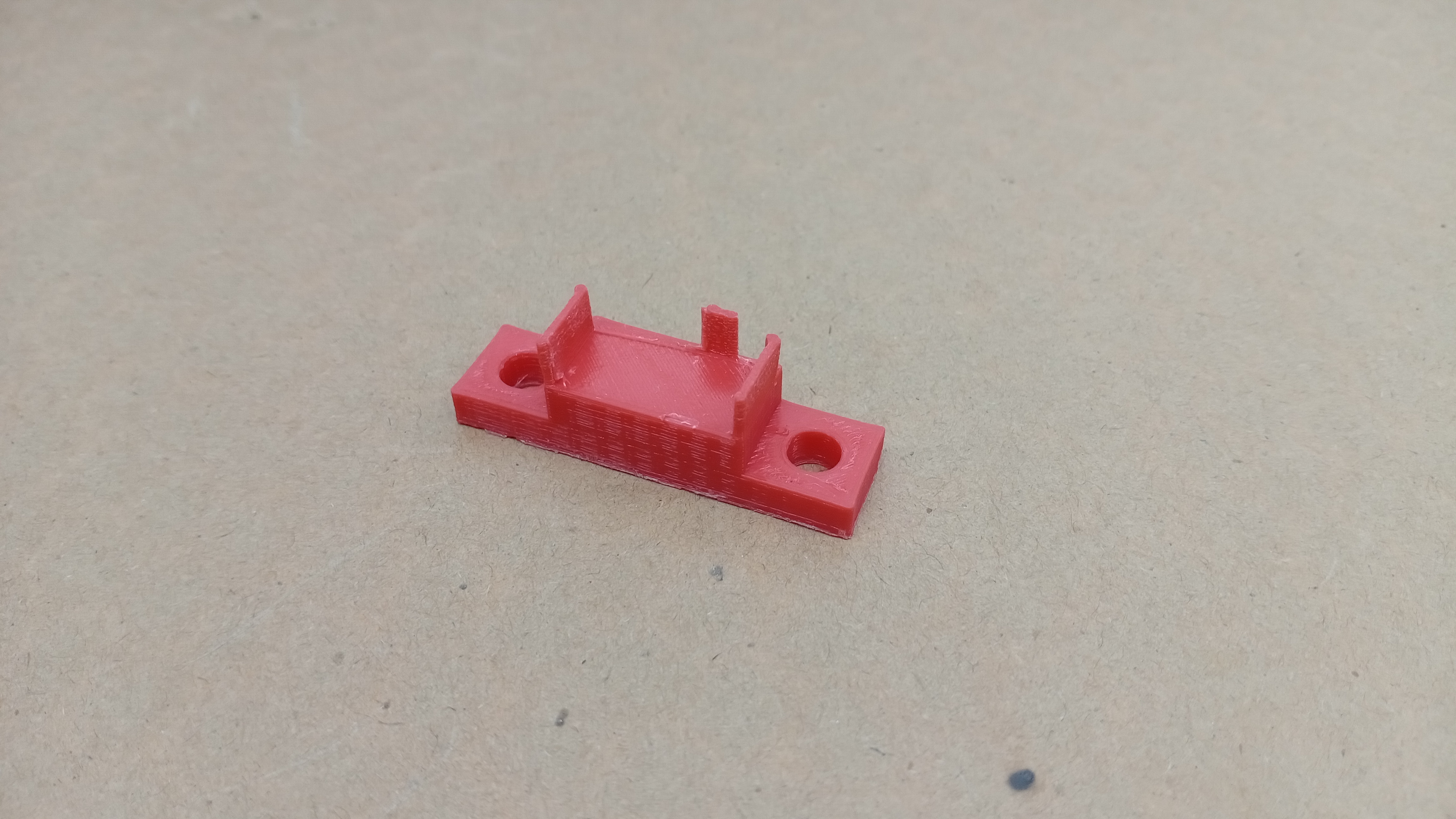
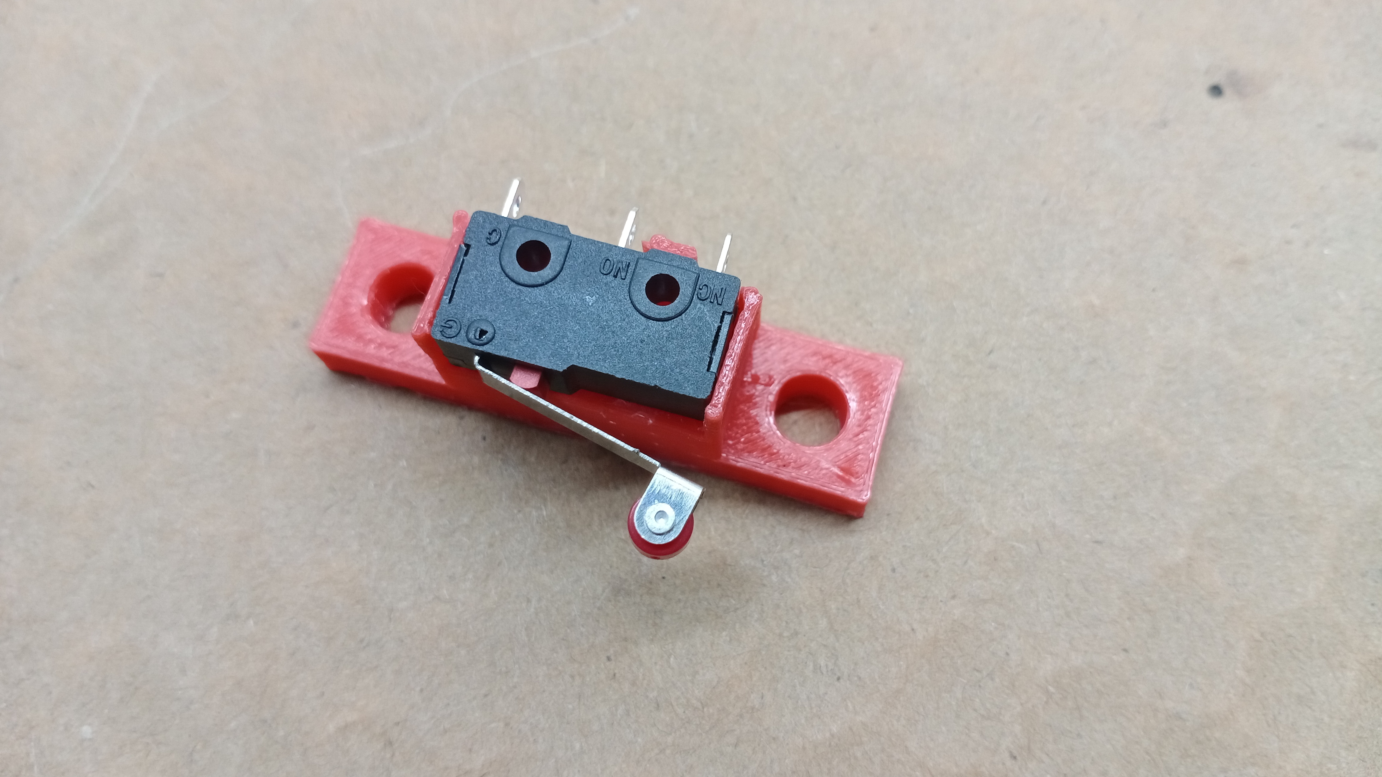
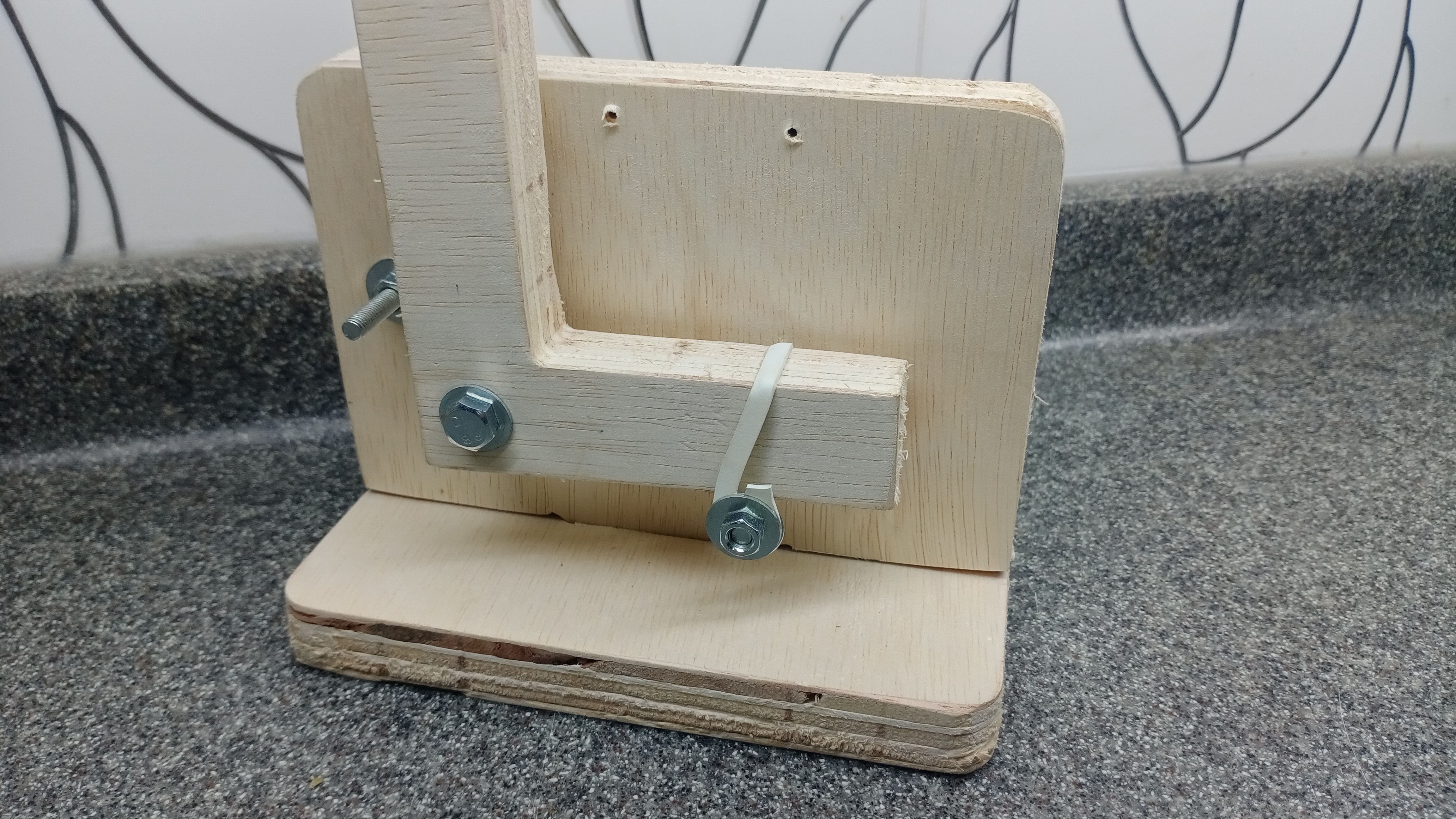
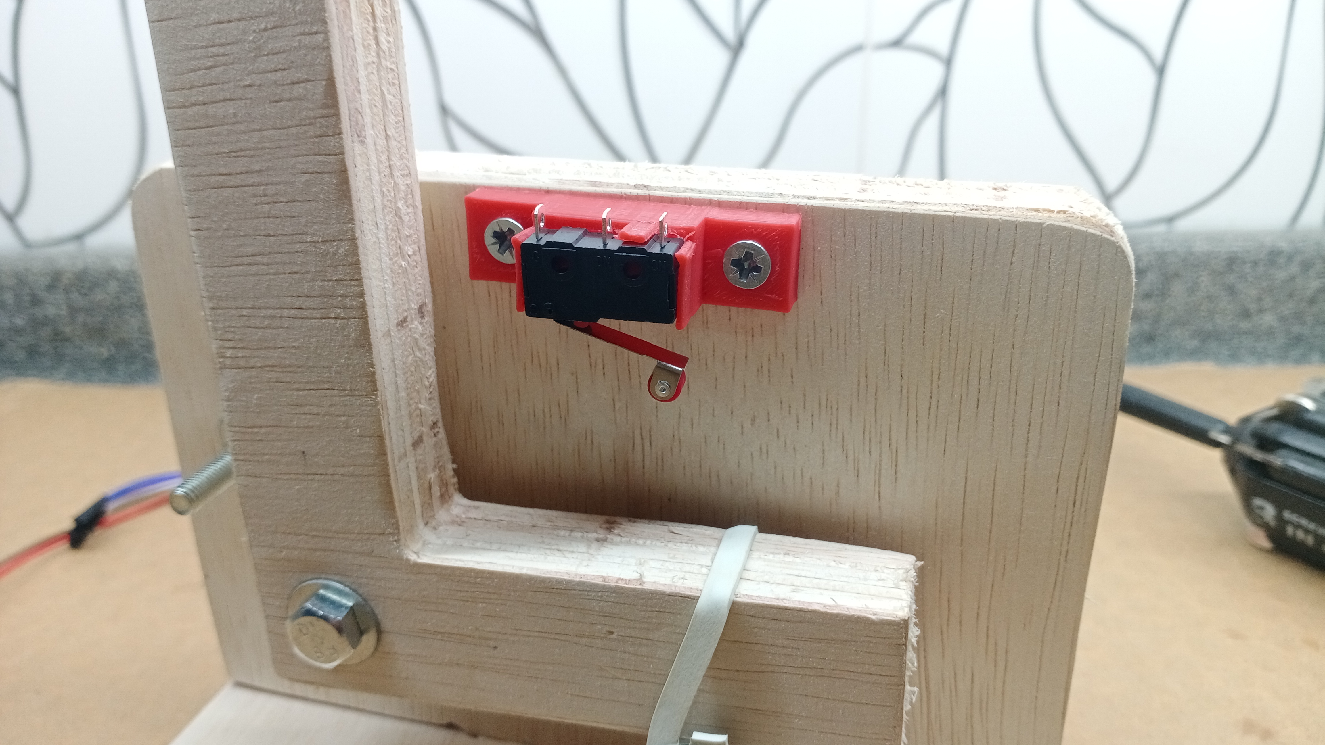
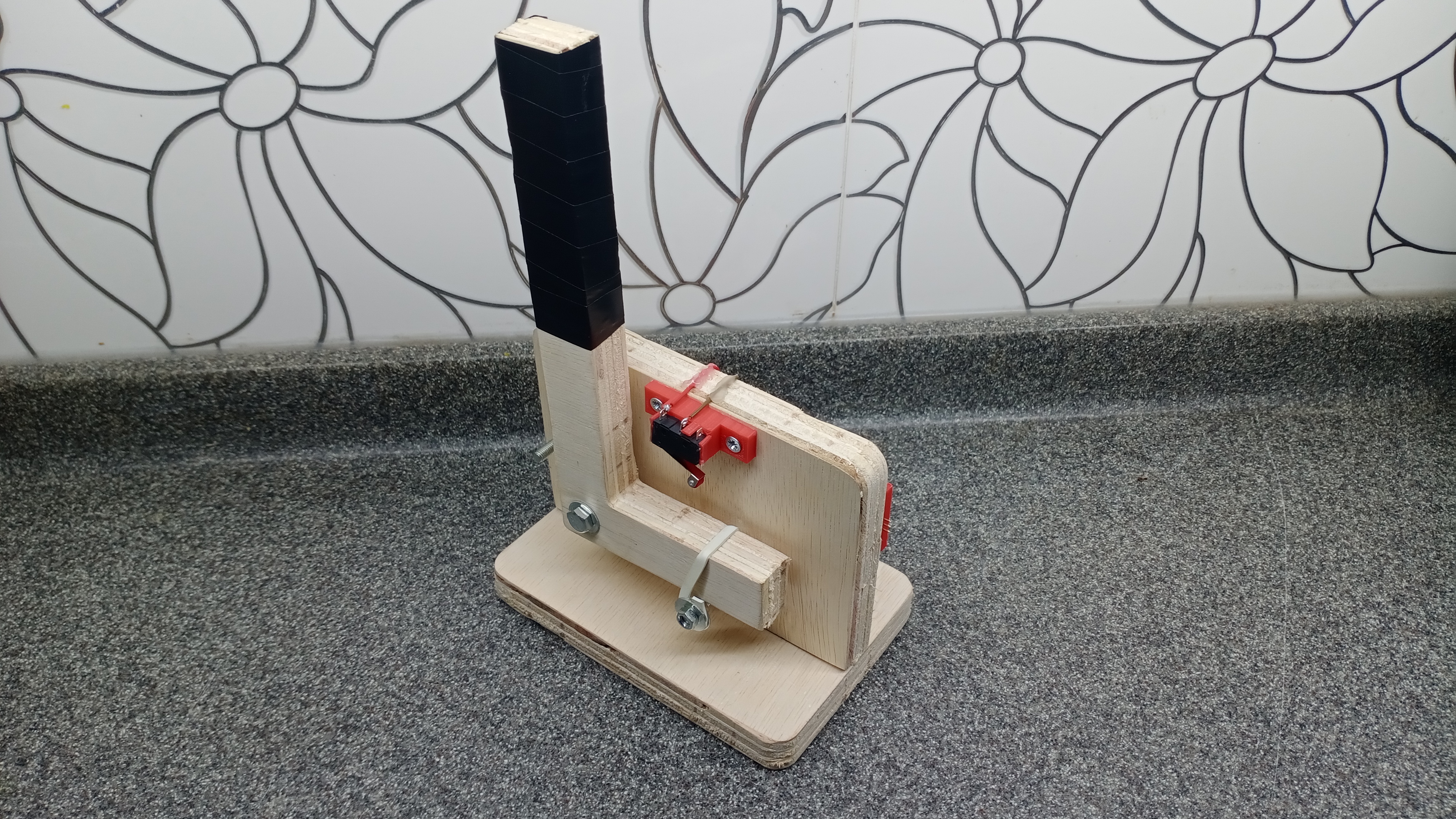
Limit Switch mount
The limit switch would need to seat at the maximum travel of the handle
.png)
Coding
The original plan was to use interfacing programming to read out the values of the potentiometer. It can be represented with a simple graph. However, I forgot to add a FTDI header to my PCB board. I’m not able to send information from the board to software. I’m not able to read the data from the potentiometer.
When the handle reaches its maximum travel, it will actuate the limit switch. Limit switch will activate the flashing led. This is to show that it has reach its maximum travel.
.png)
Assembly
I used fasteners to assemble the handbrake as it needs to be strong. I also used hot glue to tidy up the cables. For the force feedback, I used a thick rubberband pressed between washers. I wrapped the top of the handle with tape to make the grip comfortable to hold.
Hero Shots
Presentation
BOM
.png)