EP1001
Interface & Applications programming
I used an example from Arduino to see how interfacing works. First I need to install a software called Processing. It is similar to Arduino IDE. There will be 2 codes, processing is for computer input and Arduino IDE for PCB board output.
Next, coding for Arduino. I need to include SoftwareSerial library to link the PCB to computer. Define RX and TX. I uploaded it using UPDI programmer. Once done, I will remove the UPDI and connect the PCB directly to FTDI.
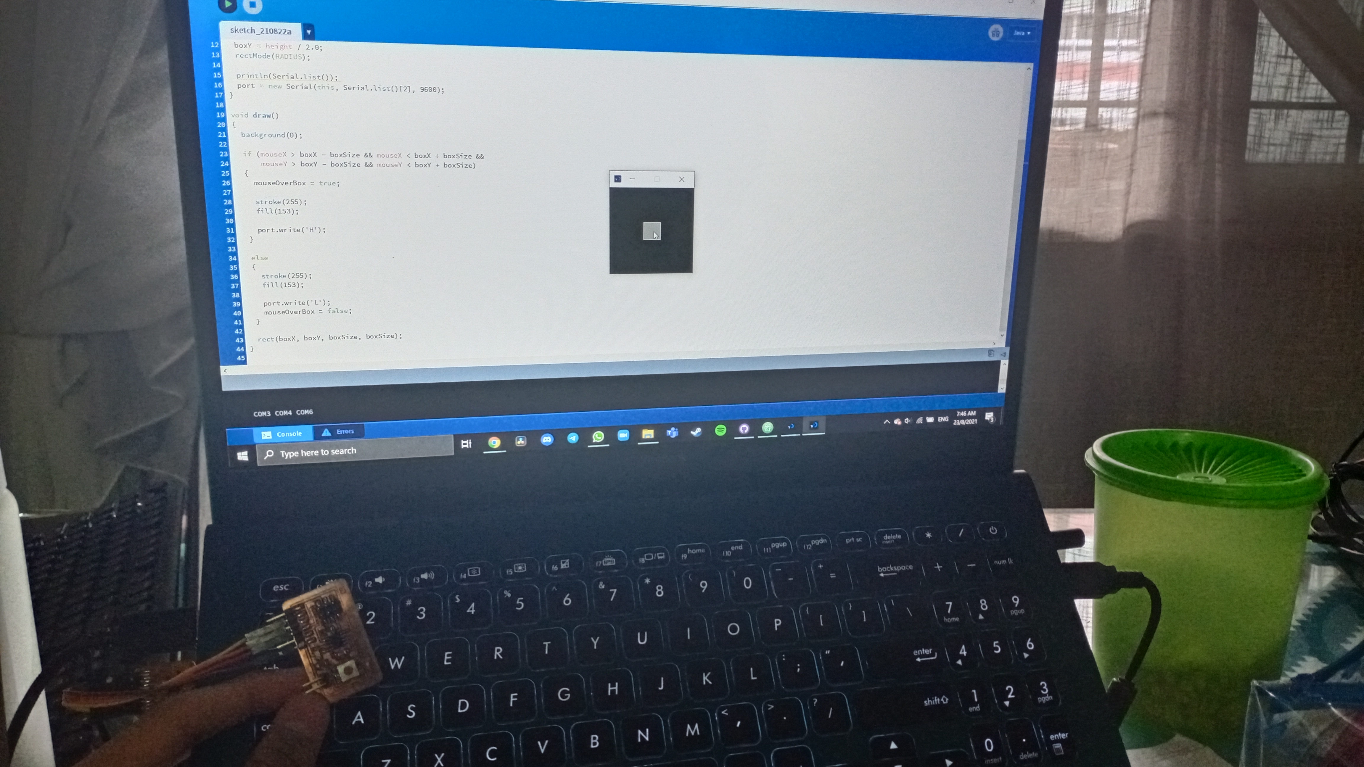
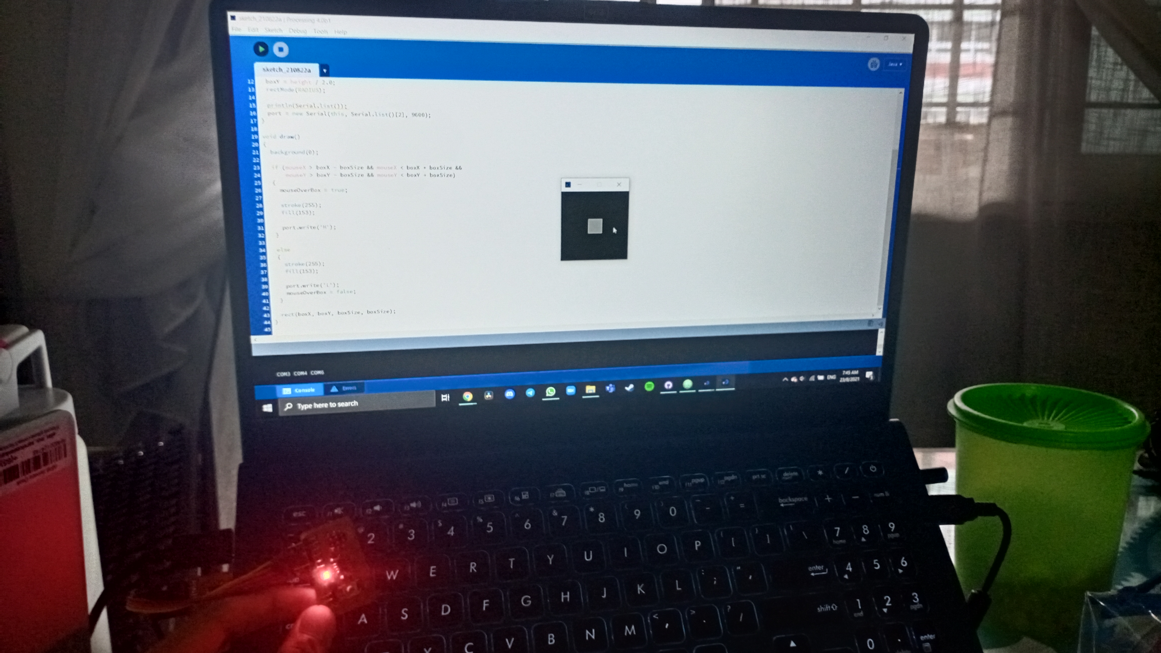
Coding for Processing. The code includes recognizing com port of PCB, creating rectangle box and Mouse cursor.
When the mousecursor is on the box, the led on PCB will not light up. When the mousecursor is off the box, the led will light up.
.png)
.png)
.png)

