EP1001
Electronics Production
PCB fabrication
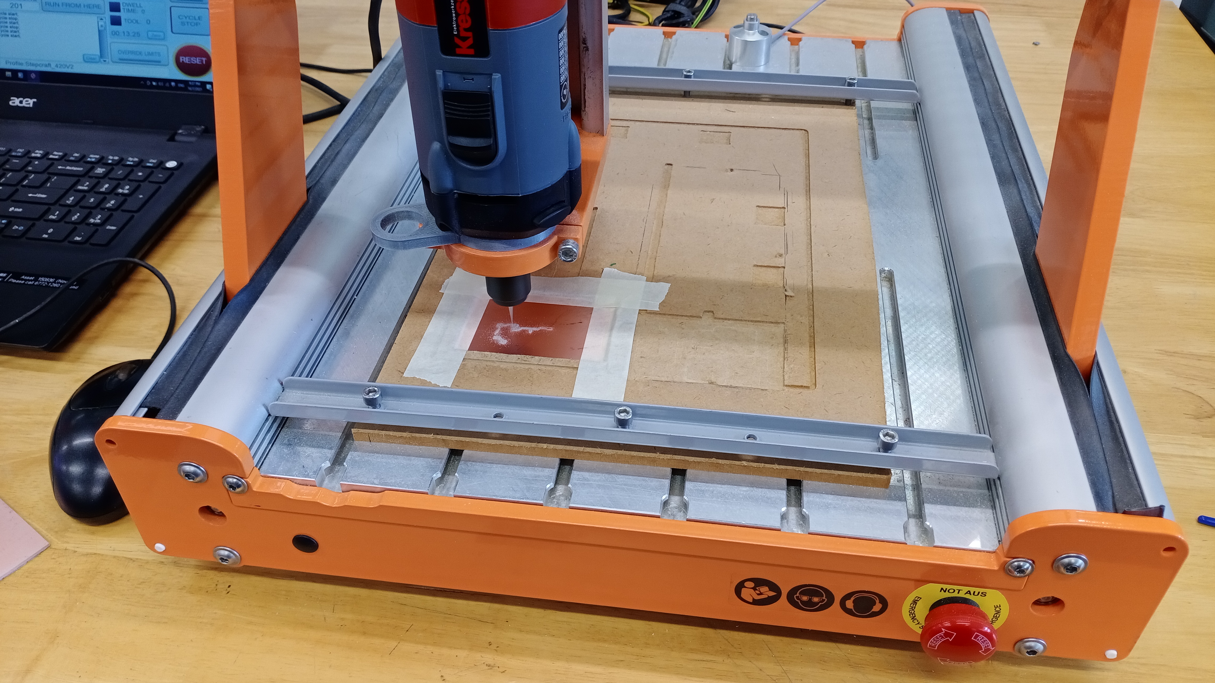
In FabLab, We use machining method to fabricate the PCB board. FabLab uses the Stepcraft 420. It is a mini CNC machine that uses a dremmel as cutting tool.
- Tools
- 0.25mm, 0.4mm, 0.8mm(Usually for outline)
- V-bits( Used for traces)
PCB materials
We are supplied with copper plates for PCB. The cutter will remove material to create channels and component connectors
Assembly
After milling the PCB board, we will need to add components to the PCB. This can be done through soldering. Soldering is basically joining two wires or components by melting solder. We use an iron to heat the solder which then cools to form a strong bond between wires and components. It is similar to welding.
CAM
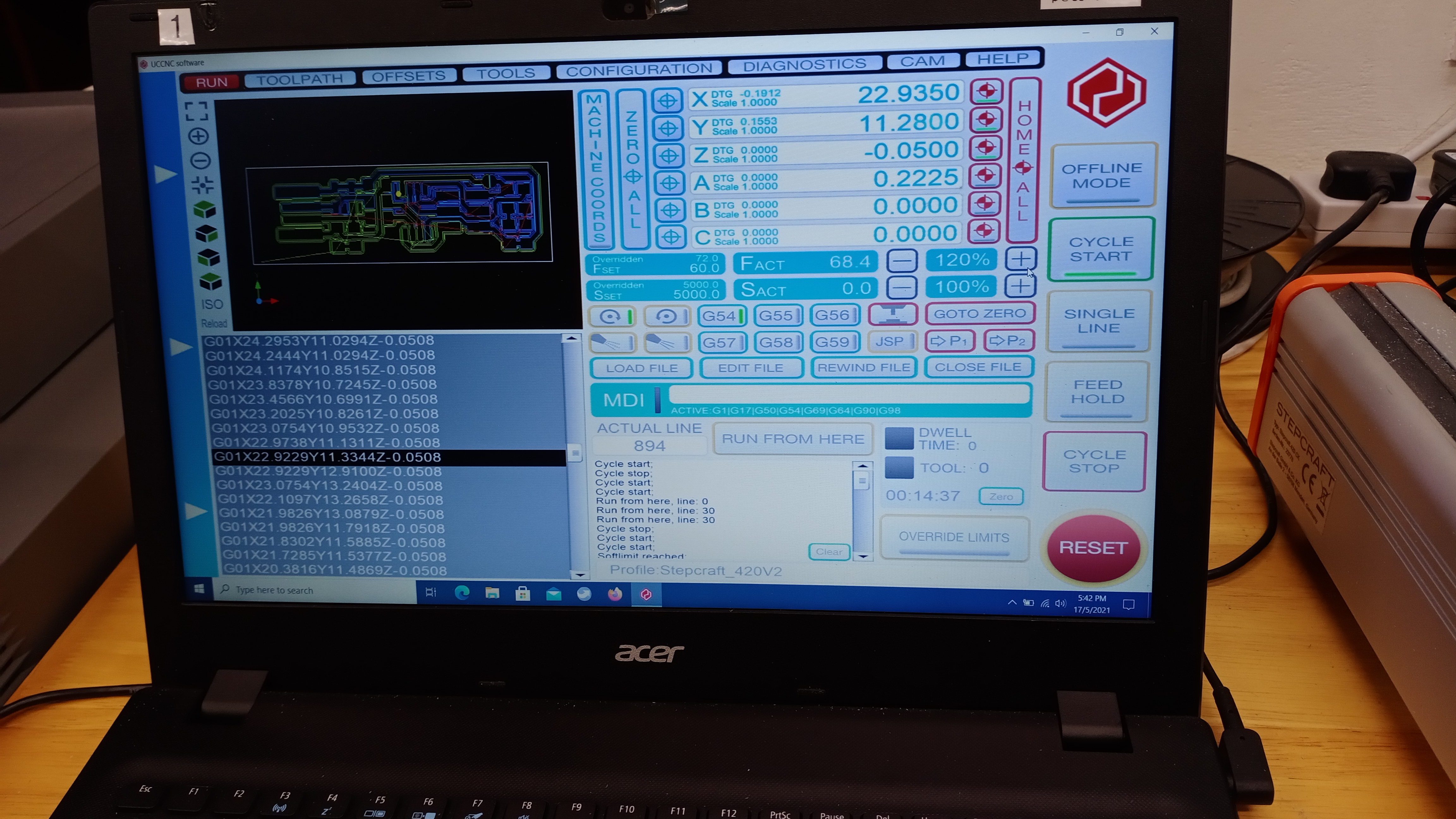
In order to mill the PCB, the machine needs a g-code file. We are using this mods to generate g-code from a png file. It is quite simple to use:
- Upload PNG of traces or outline
- Select the settings
- Generate g-code
We can use this ncviewer to inspect the g-code and stimulate the process.
Assignment
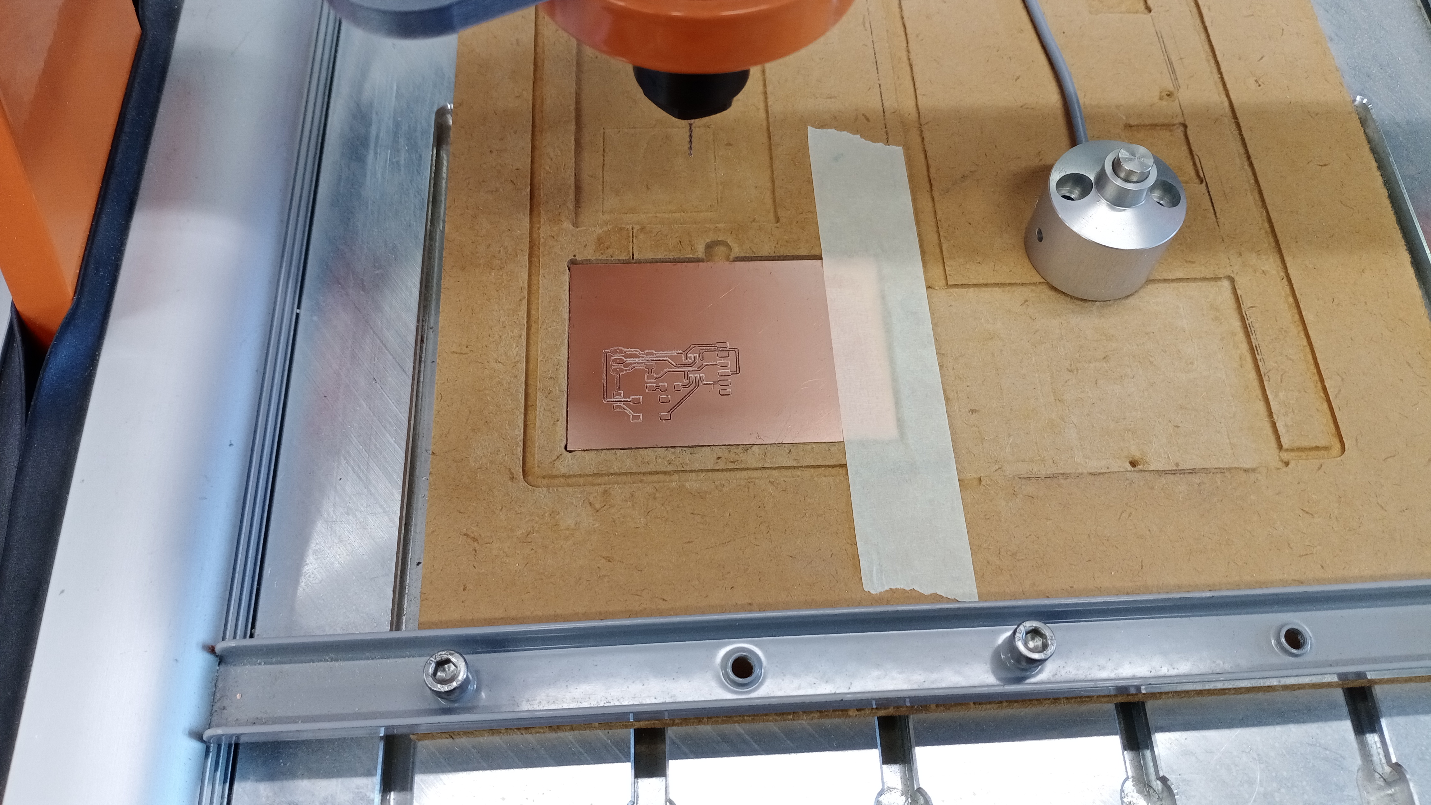
We were tasked to fabricate FTDI and FTDI-to-UPDI interface board. First we need to generate the g-code. Once we have all the g-codes, we’ll need to inspect them by using ncviewer. After inspection, it is time for CNC machine.
- Clean the mill table
- Paste Copper plate on mill table, use double-sided tape. Make sure that the plate does not move under load
- Use correct tool bit for operations
- Make sure to check the tool bit for any damage before using it. It would be better to use newer tool bit. If you don’t use the right tool bit you would get massive burr, not ideal for channels.
- Calibrate the machine coordinates and workpiece origin
- Start the operation
- Need to vacuum the copper dust so that it does not interfere with cutting.
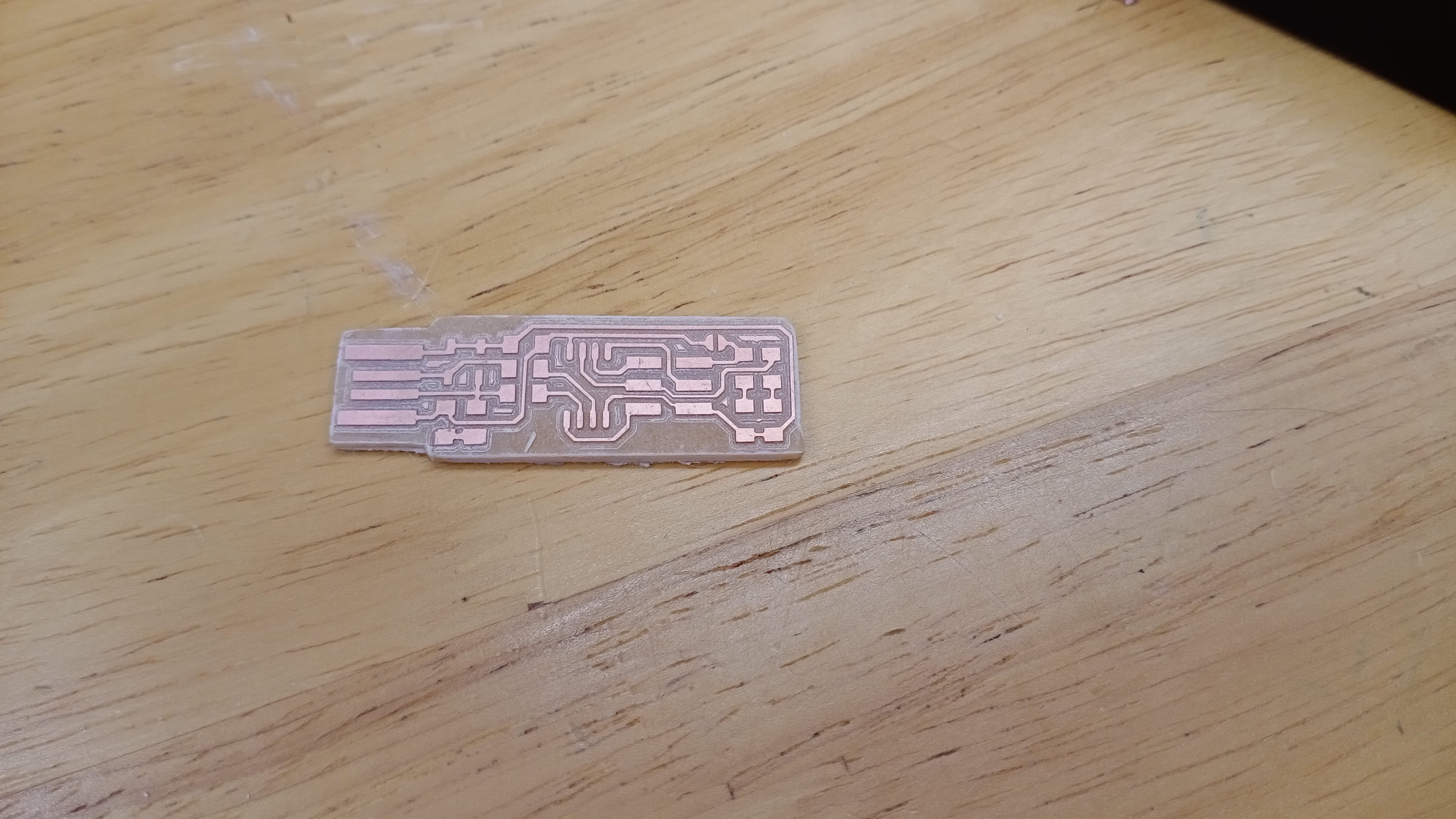
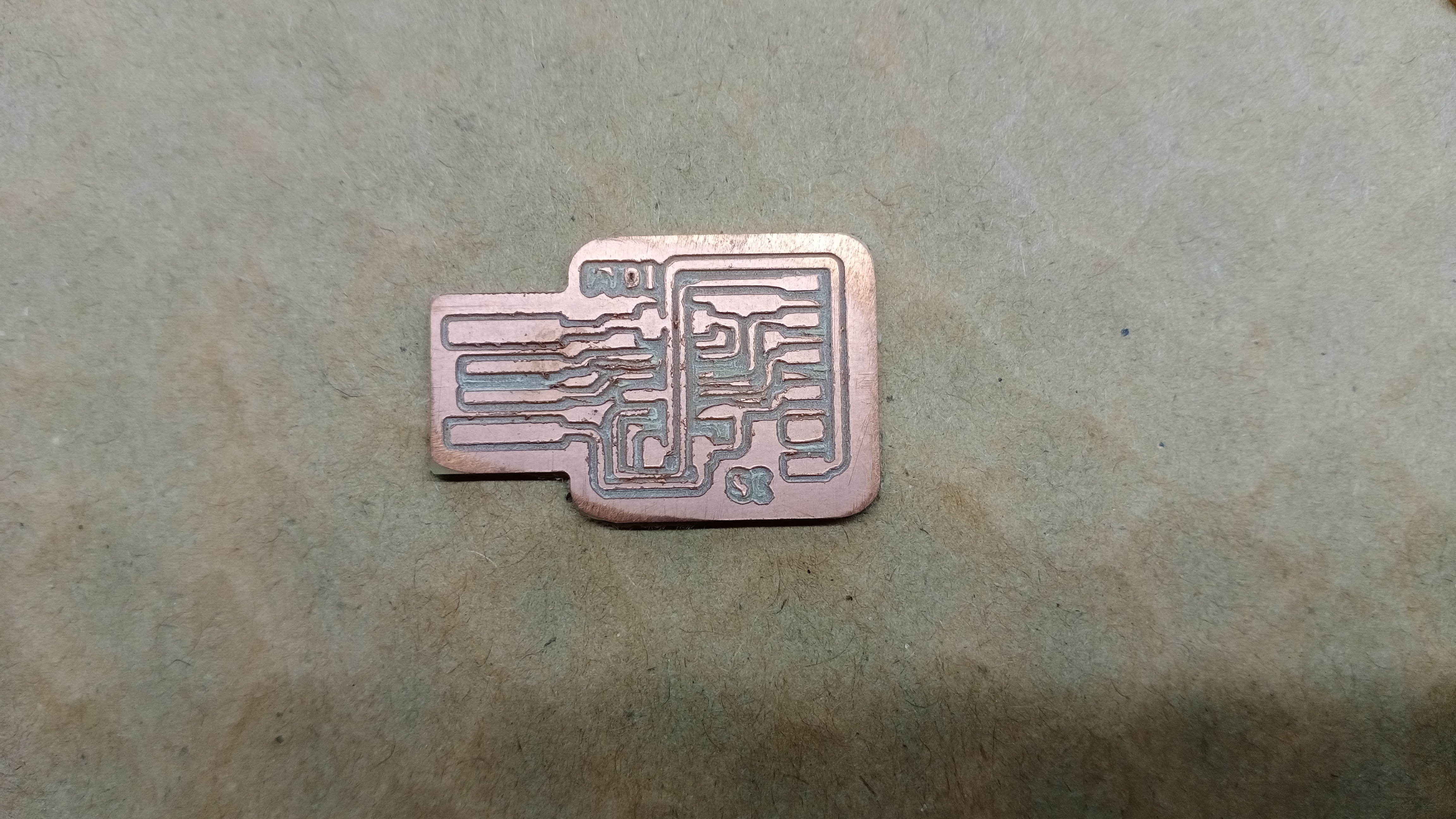
After milling the board, We need to prepare the board for soldering. I’ll sand the copper side to remove any burr.
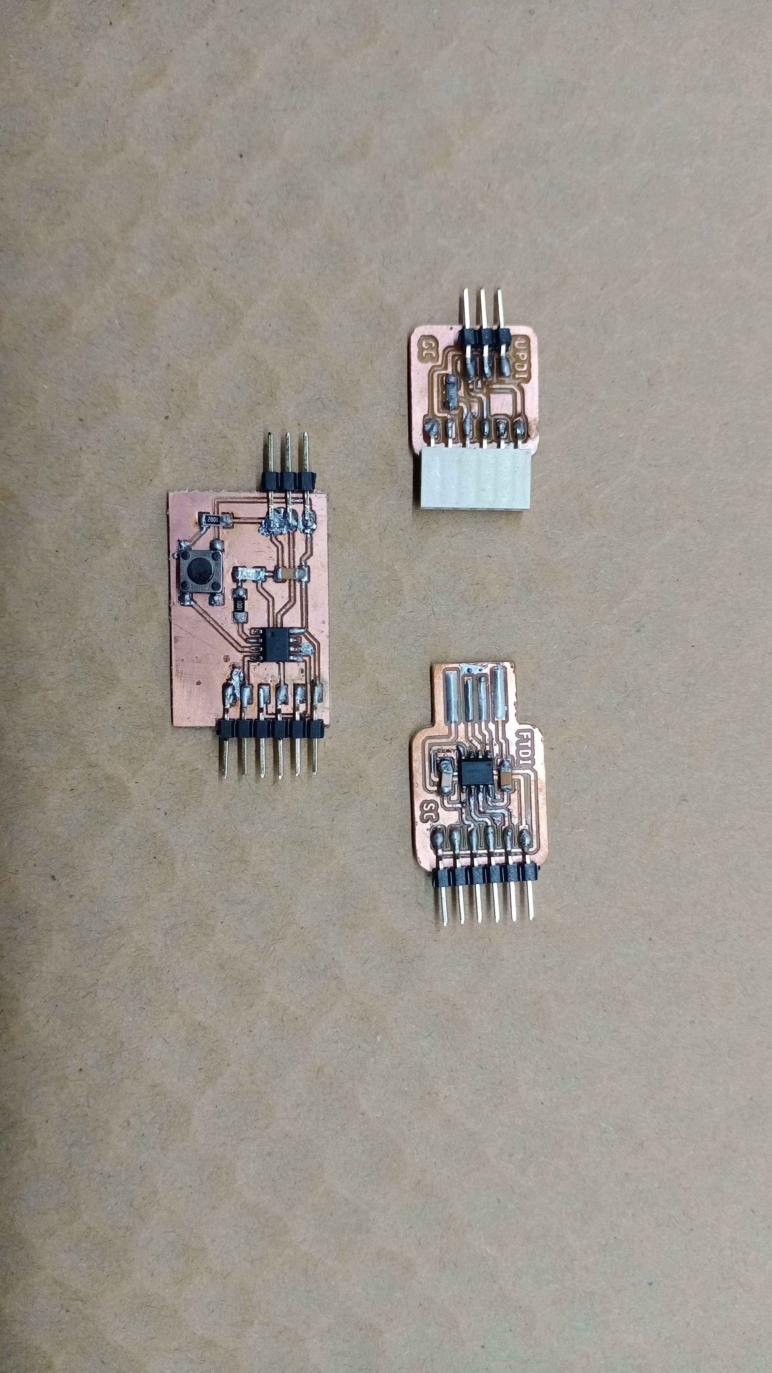
I soldered the smaller components first like resistor, capacitor and LED. Then I moved on to the bigger components like microcontroller, pin headers and switches. We can refer to the schematic to make soldering easier. We also need to make sure that the orientation of the components are correct. For example, the Attiny412 has a dot that represents pin 1.
Here are the boards. My soldering could be better. It was difficult to solder the smaller component. You need a fine tip to make it slightly easier.