EP1000
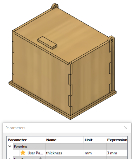
My Box
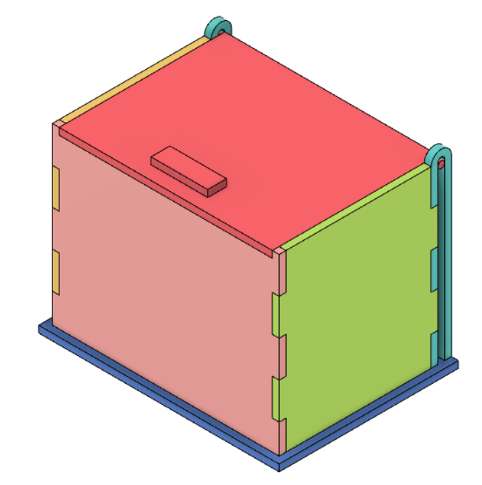
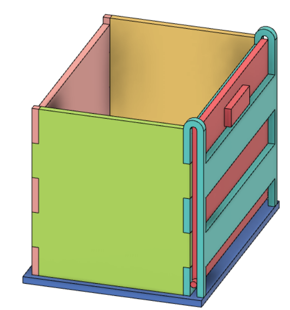
I can’t really explain how it opens and closes so here is visual
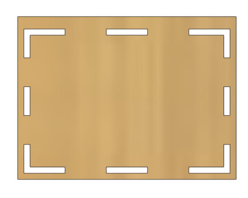
Step 1: Front
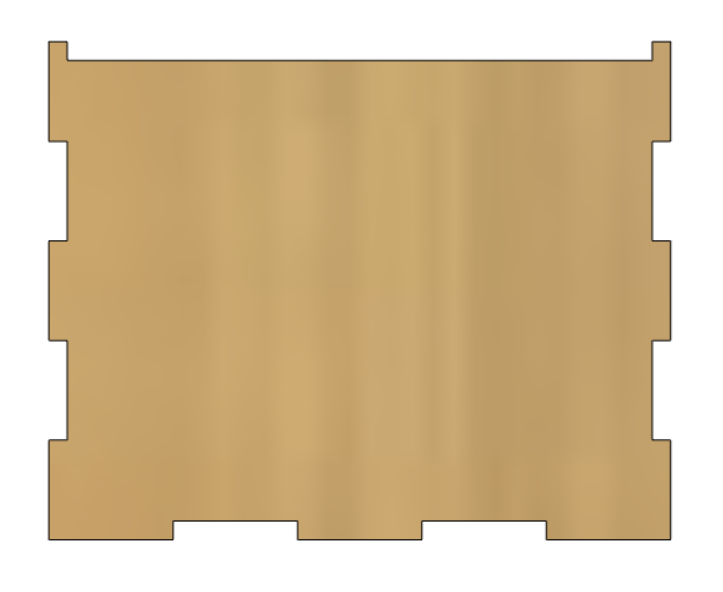
- Create new component and sketch on ZX plane
- Draw rectangle from the origin. Dimension rectangle using user parameters
- Draw a line on the left side of rectangle and 2 lines on bottom side of rectangle. Dimension them to the thickness of the box. Draw 2 rectangles between the lines, for the tabs. Dimension them using a formula in terms of the height and length
- Mirror the tabs on the left side to right
- Extrude the rectangle without the tabs
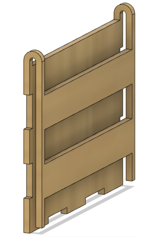
Step 2: Left
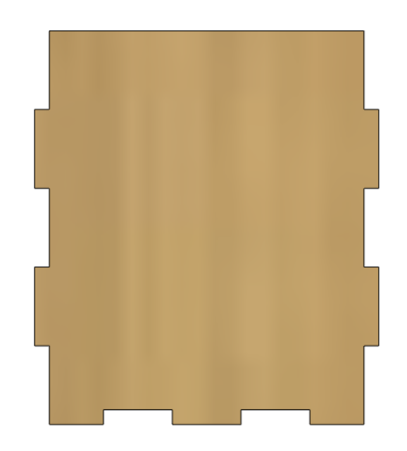
- Create new component and sketch on the left face of the front component
- Draw big rectangle. Use colinear to constraint the sides. Dimension the width of rectangle
- Similar to step 1, Add tabs on all sides except the top
- Extrude it without the tabs
- Mirror front and left using construction midplane
- Combine them. Left and Right are the cutting tool
Step 3: Base
- New component and sketch on bottom face of any of the component
- Draw rectangle. Dimension them so that they have allowance on all sides, I use thickness
- For the back side, add extra allowance
- Extrude then combine. the sides will be cutting tool
Step 4: Top
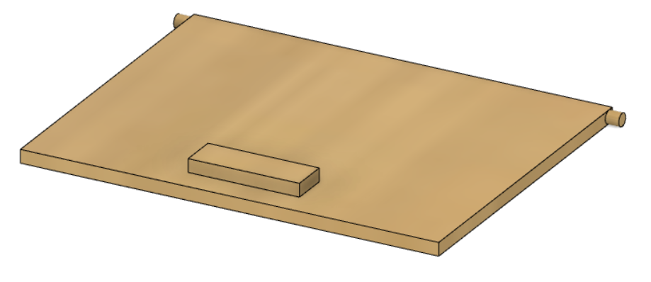
- New component and sketch on top face of component
- Draw rectangle and Dimension it. Similar to base, extend the backside
- Extrude
- New sketch on top face. Draw small rectangle, this is the handle. Dimension it then extrude
Step 5: Back
I can’t really explain so here is visual
Why use parameters
| 3mm thickness | 5mm thickness |
|---|---|
 |
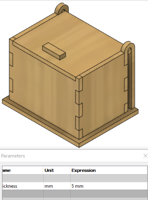 |
I’m able to change the thickness of the box by editing the user parameter instead of edit sketch